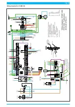
Page 42
Causes and remedy of faults
Signal on site
Fault
Cause
Remedy
Green LED
"Operating voltage /
Spänning"
(
19
) does not illuminate
and
display of the
ACS
(
18
) is dark.
Equipment does not receive operating
voltage.
Operating voltage is not switched on.
Faulty wiring.
Power plug is not fitted correctly.
24 V (
26
) power pack is defective.
Switch on operating voltage.
Check wiring,
retighten terminal screws.
Check power plug.
Replace power pack.
Green LED
"Operating voltage /
Spänning"
(
19
) does not illuminate
Green LED „DC OK” in 24 V (
26
) power
pack does not illuminate.
24 V (
26
) power pack does not receive
operating voltage.
24 V (
26
) power pack is defective.
Green LED "Operating voltage / Spän-
ning" (
19
) is faulty.
Check wiring, retighten terminal
screws at power pack.
Replace power pack.
Replace LED.
Display of ACS (
18
) is dark.
ACS (
18
) does not work.
Screensaver is active.
Faulty wiring,
or
2 4 V (
26
) power pack
does not receive operating voltage.
24 V (
26
) power pack is defective.
Microfuse „DC” (
B
) at MFR (
45
) is
defective.
ACS is defective.
Press any key of the ACS.
Check wiring, retighten terminal
screws at power pack.
Replace power pack.
Replace microfuse:
type M 2.0 A
Replace ACS.
Red signal-LED „
Fault / Fel“
(
20
) on
the instrument panel (
2
) illuminates.
Red Signal-LED „
F“
(
48
) on the MFR
(
45
)
illuminates
.
Humidity fault = relative humidity of
output air is unadmissibly high.
Maintenance of air dryers (
35
) was not
carried out.
Pressure limiting valve (
38
) is set
incorrectly or defective.
Double non-return valve (
39
) is defec-
tive.
Condensate discharge hose (
10
) is bent
or blocked, its diffusor is clogged.
Electric triggering of solenoid valves
(
36
) of air dryers (
35
) fails or is in
wrong clock pulse.
Solenoid valves (
25
) are defective or
worn out.
Carry out maintenance of air dryer, see
page 40.
Set pressure limiting valve properly,
see page 33, replace if necessary.
Check amount of regeneration air (270 -
300 l/h), replace double non-return
valve (
39
) if necessary, see page 41.
Check hose, replace diffusor if neces-
sary.
Check cycle time, see page 31.
Watch relay KY1 u. KY2, check wiring
and plugs of solenoid valves.
Replace solenoid valves
Red signal-LED „
Fault / Fel“
(
20
) on
the instrument panel (
2
) illuminates.
Red Signal-LED „
F“
(
48
) on the MFR
(
45
)
flashes
.
Humidity sensor (
41
) of MFR is defec-
tive or wiring is defective.
Check wiring, replace humidity sensor
if necessary.
Red signal-LED „
Fault / Fel“
(
20
) on
the instrument panel (
2
) illuminates.
Red Signal-LED „
T-runtime“
(
53
) on
the MFR (
45
)
illuminates
.
Runtime alarm: compressors runs for a
longer time than preset (see page 31)
Equipment is permeable.
Pressure monitor (
40
) is defective or
set wrong.
Compressor safety valve (
23
) blows off.
Safety valve „high pressure” (
29
)
blows off.
Safety valve „cable pressure” (
24
)
blows off.
Solenoid valves (
36
) of air dryer (
35
) do
not close.
Double non-return valve (
39
) is con-
taminated or blocked.
Compressor ot compressor hose is
permeable.
Compressor output is insufficient.
Thermal protection in the coil of the
compressor motor has initiatied.
Compressor’s electrical connection is
faulty.
Check hoses for permeability.
Set pressure monitor or replace it (see
page 32).
Test opening pressure (7 bar, typical
value at ACS display is 5.7 - 6.1 bar)
and replace safety valve if necessary,
Check hoses for clogging.
Replace safety valve.
Set cable pressure (see page 30),
replace safety valve if necessary.
Check solenoid valves, replace them if
necessary.
Check amount of regeneration air (270 -
300 l/h), replace double non-return
valve if necessary, see page 41.
Seal/replace permeable parts of com-
pressor, hoses or connectors.
Replace air-intake filter or compressor
if necessary.
compressor overheating: check fan
(
27
) and aeration
Check compressor pressure
Replace compressor if its bearings are
worn or defective.
Check wiring, retighten terminal
screws.
Red signal-LED „
Fault / Fel“
(
20
) on
the instrument panel (
2
) illuminates.
Green Signal-LED „
AC“
(
50
) on the
MFR (
45
)
is dark
.
Microfuse „AC” (
A
) at MFR (
45
) is
defective.
Replace microfuse:
type M 0.315 A
Summary of Contents for RTS 1000
Page 15: ...Page 15 39 35 37 36 36 23 42 28 27 24 6 33 38 40 41 32 22 29 25 8...
Page 21: ...Page 21...
Page 47: ...Page 47 7 16 14 15 15 18 17 13 20 24 8 23 10 6 9 4 22 21 19 8...
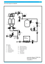
Page 51: ...Page 51 Pneumatics diagram Nr 074891 000...
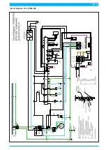
Page 53: ...Page 53 Circuit diagram Nr 074880 000...


