PAGE 25
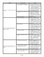
TROUBLESHOOTING
Problem
Possible Cause
Solution
1. No Display on PC Board
a. No power at electric outlet
a. Repair outlet or use working outlet
b. Control valve Power Adapter not plugged
into outlet or power cord end not
connected to PC board connection
b. Plug Power Adapter into outlet or
connect power cord end to PC Board
connection
c. Improper power supply
c. Verify proper voltage is being delivered
to PC Board
d. Defective Power Adapter
d. Replace Power Adapter
e. Defective PC Board
e. Replace PC Board
2. PC Board does not display correct time of day
a. Power Adapter plugged into electric outlet
controlled by light switch
a. Use uninterrupted outlet
b. Tripped breaker switch and/or tripped GFI b. Reset breaker switch and/ or GFI switch
c. Power outage
c. Reset time of day. If PC Board has
battery back up present the battery
may be depleted. See Front Cover
and Drive Assembly drawing for
instructions.
d. Defective PC Board
d. Replace PC Board
3. Display does not indicate that water is
flowing. Refer to user instructions for how the
display indicates water is flowing
a. Bypass valve in bypass position
a. Turn bypass handles to place bypass in
service position
b. Meter is not connected to meter
connection on PC Board
b. Connect meter to three pin connection
labeled METER on PC Board
c. Restricted/ stalled meter turbine
c. Remove meter and check for rotation or
foreign material
d. Meter wire not installed securely into three
pin connector
d. Verify meter cable wires are installed
securely into three pin connector
labeled METER
e. Defective meter
e. Replace meter
f. Defective PC Board
f. Replace PC Board
4. Control valve regenerates at wrong time of
day
a. Power outage
a. Reset time of day. If PC Board has
battery back up present the battery
may be depleted. See Front Cover
and Drive Assembly drawing for
instructions.
b. Time of day not set correctly
b. Reset to correct time of day
c. Time of regeneration set incorrectly
c. Reset regeneration time
d. Control valve set at immediate
regeneration
d. Check programming setting and reset to
DELAYED (for a delayed regen time)
e. Control valve set at (d immediate) e. Check programming setting and reset to
DELAYED (for a delayed regen time)
5. Time of day flashes on and off
a. Power outage
a. Reset time of day. If PC Board has
battery back up present the battery
may be depleted. See Front Cover
and Drive Assembly drawing for
instructions.
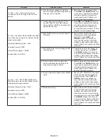
6. Control valve does not regenerate
automatically when the
REGEN
button is
depressed
a. Broken drive gear or drive cap assembly
a. Replace drive gear or drive cap
assembly
b. Broken Piston Rod
b. Replace piston rod
c. Defective PC Board
c. Replace PC Board
7. Control valve does not regenerate
automatically but
does
when the
REGEN
button
is depressed and held.
a. Bypass valve in bypass position
a. Turn bypass handles to place bypass in
service position
b. Meter is not connected to meter
connection on PC Board
b. Connect meter to three pin connection
labeled METER on PC Board
c. Restricted/ stalled meter turbine
c. Remove meter and check for rotation or
foreign material
d. Incorrect programming
d. Check for programming error
e. Meter wire not installed securely into three
pin connector
e. Verify meter cable wires are installed
securely into three pin connector
labeled METER
f. Defective meter
f. Replace meter
g. Defective PC Board
g. Replace PC Board
Summary of Contents for 7-LX-100
Page 29: ...PAGE 29 NOTES ...


