background image

LEGACY FG

033-0004

Page  S.29

REV. 0/04-23-2007

Lancair International Inc., Represented by Neico Aviation Inc., Copyright 2007 Redmond, OR 97756

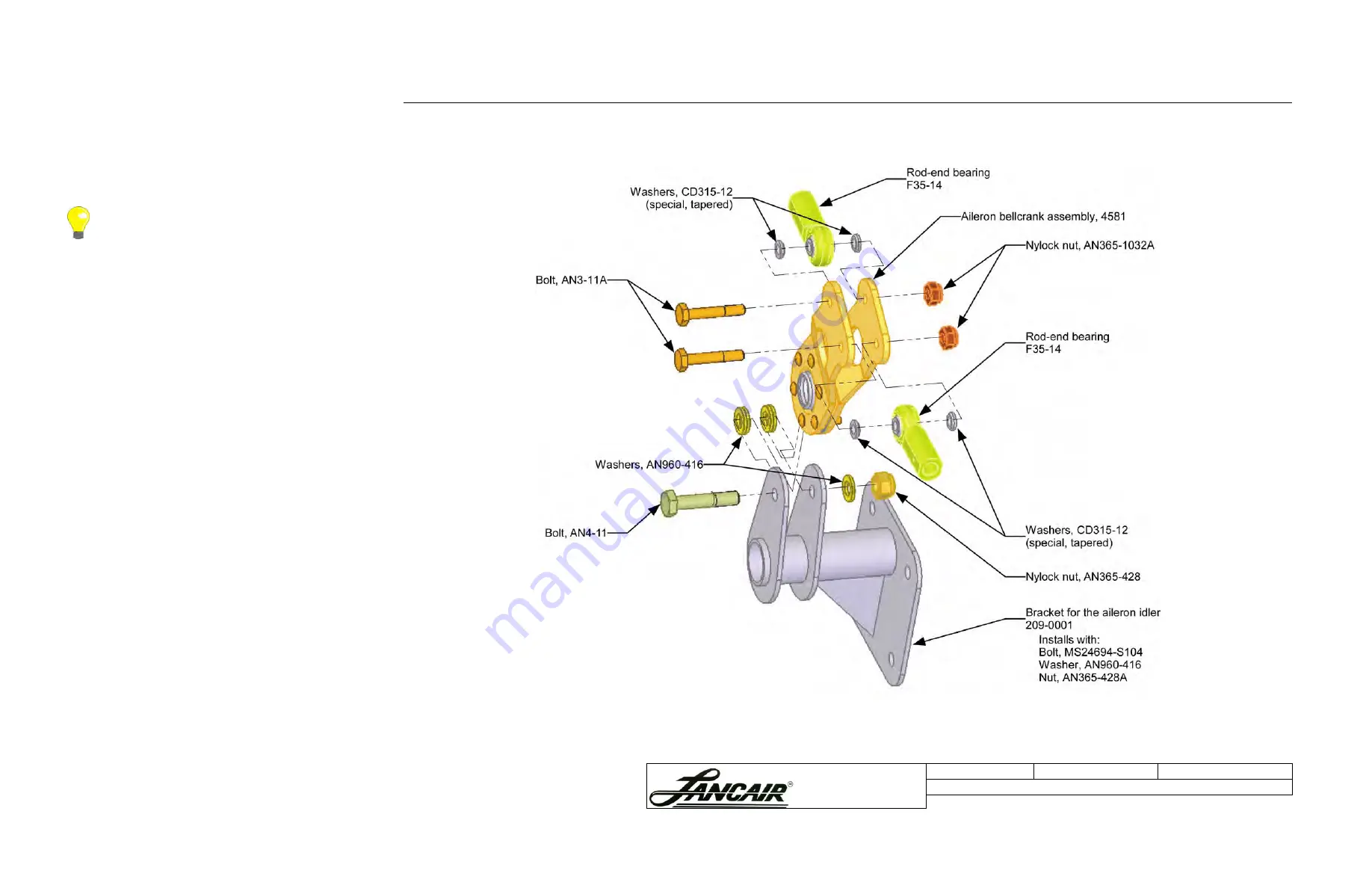
S.7  Installing the Idler Assembly

The idler assembly in the Legacy FG is located differently 
than in the retractable Legacy.

S.7.A  Aligning the Idler’s Base Bracket 

Steps...

1. Assemble the aileron idler.
2. Clamp the aileron idler bracket (209-0001) to the wing 

spar.

3. There are four dots on the spar to help locate the base 

bracket. Clamp the bracket over these dots so a dot can 
be seen through each bolt hole.

4. Install the aileron assembly to the base bracket.
5. Install the control stick assembly per page 6-3 in the 

Legacy Assembly Manual

 and follow the rigging 

procedure.

Setting the Controls to Neutral

The basis for rigging the aileron control system is to set the 
stick, idlerarm, bellcrank and the aileron to neutral. Then 
the control tubes are adjusted accordingly.

Steps...

1. Set all inboard controls to neutral.
2. Connect the inboard push-pull tube to the rod-end 

bearing.

3. Move the control sticks through their entire range of 

motion, including the maximum elevator travel.

Connecting the Rod-end Bearing to the Push-pull Tube

Rod ends should always maintain at least five threads 
engaged onto the end of the push-pull tube. The simplest 
method for connecting a rod-end bearing is as follows:

• Turn the rod end onto the end of the push-pull tube, 

counting each turn, until it bottoms out.

• Turn the rod end out by 1/2 the total turn count.
• This should be at least or greater than five turns.
• Always check the witness hole.

To correctly locate the aileron assembly, the controls must 
be set to neutral and tested prior to finishing the 
installation of the base bracket.

Figure S.7.A.1 Idler base bracket and assembly 

Summary of Contents for Legacy Fixed Gear

Page 1: ...irects you to remove and replace the pages affected by the revision Add directs you to insert the pages shows and R to remove the pages Pages Affected Revision and Date Action Description S 1 1 08 10 2007 R R Updated table of contents for new page S 23B S 2 S 4 1 08 10 2007 R R Updated part number lists for changes made in supplement s instructions and graphics S 8 S 13 S 21 S 23 S 32 S 33 1 08 10...

Page 2: ...r Modifications Ch 6 Aileron Controls B 3 on page 6 6 Fuel System Modifications Ch 4 Fuel Systems C Fuel Supply Lines on page 4 5 E Fuel Return Lines on page 4 9 Appendix Alternate Air Assembly for the IO 360 New Information New Information S 1 Introduction S 1 S 2 Parts Used in this Supplement S 2 S 3 Preparing for the Main Gear Installation S 5 S 3 A Leveling the Fuselage S 5 S 4 Installing the ...

Page 3: ...left 8 7045RA 1 Main gear pant brake cover right 9 7048L 1 Fuselage gear fairing left 10 7048R 1 Fuselage gear fairing right Nose Gear Item Part Number QTY Description 1 212 0041 1 Nut plate nose fork 2 212 0073 2 Plate Keeper Nose Gear 3 229 0005 1 Link Nose Gear 4 432 0002 1 Nose Gear Cylinder 5 433 0000 1 Nose Fork 6 3455 1 Nose gear fearing mounting plate 7 4717 01 1 Pivot Bearing Block Left 8...

Page 4: ...AN960 416 12 Washer 20 AN960 416L 4 Washer Thin Nose Gear Continued Item Part Number QTY Description 21 AN960 516 18 Washer 22 AN970 4 4 Large Area Washer 23 MS24694 S154 8 Screw countersunk Fuel System Item Part Number QTY Description 1 4805 2 Fuel hose 8 straight to straight 2 2240 6 8S 1 Bulkhead fitting 3 8 NPT to 8 flare 3 C5205x8x4 1 Pipe connector fitting 1 2 tube 1 4 male pipe 4 C5365x8 1 ...

Page 5: ... 1 Spring 18 K1000 08 12 Nut Plate 19 MS20001 1 Hinge 20 MS21042 06 1 Stop Nut Plated 21 MS21042 08 4 Stop Nut Plated 22 MS21042 4 1 Nut 23 101 0050 MS24693 C32 1 Socket head Screw Countersunk 24 MS24693 S50 3 Screw Plated 25 AN4 10A MS24694 S103 1 Bolt Screw Countersunk Alternate Air Assembly For TNIO 360 390 as installed in Supplement Appendix Item Part Number QTY Description 1 08 10 2007 ...

Page 6: ... allow room for the gear legs Allow approximately 32 from the floor to the bottom of the wing stubs Secure the fuselage in its level position 2 Mark a center line on the floor For more information on locating a center line see Chapter 7 page 7 3 of the Legacy Assembly Manual This will refresh your memory on drawing a center line Figure S 3 A 1 Leveling the fuselage S 4 Installing the Gear Legs S 4...

Page 7: ...he aileron push pull tube for clearance The aileron push pull tube must clear the upper leg attachment For information on the location and assembly of the aileron push pull tube see Chapter 6 Section B in the Legacy Assembly Manual 3 Clamp the upper leg attachment in place 4 Cut the gear leg hole so it is large enough to slide the gear leg in place 5 Insert the gear leg through the opening and int...

Page 8: ...ent in place Countersink from the front and insert a screw MS24694 S154 in each hole Add a washer AN960 516 to the back and secure with a nut AN365 528A Now you are ready to install the gear leg Attaching the Gear Leg You may have temporarily inserted the gear leg into the upper gear attachment in the previous section when you checked the angle of the leg now you will finish the installation Figur...

Page 9: ...756 Securing the Upper Leg Link Now you will finish installing the upper leg assembly by installing the upper leg link First you need to determine the fit of the upper leg link and complete a release before installing the remaining assembly See the next page for instructions Figure S 4 B 3 Securing the upper leg attachment and link to the wing spar 1 08 10 2007 ...

Page 10: ...ctions of the upper leg attachment Secure each bolt 5 From the inside mark the four bolt locations for securing the upper leg link s aft end to the inside of the aft wing spar 6 Mark and back drill four holes 7 Insert the four bolts from the inside and secure them on the aft outside of the wing stub Now you are ready to check the toe in angle as described in the next section Setting the Toe in on ...

Page 11: ...e mount has some slack and the set screw can be loosened and tightened as needed for leveling the alignment tool 4 Hang a plumb bob as shown in Figure S 4 C 2 and mark its position on the floor 5 Make a mark on the alignment tool 3 1 meter forward of the center of the end of the gear leg 6 Hang a plumb bob at this spot See Figure S 4 C 4 on the next page Note This process can also be done using a ...

Page 12: ...he plumb bob mark is 5 16 8 mm more at the 3 1 meter forward mark than the mark at the end of the gear leg Figure S 4 C 3 Top view of the gear legs the lines on the floor and the alignment tools 9 Re check the dimensions At 3 1 meter in front of the center of the axle mount the plumb bob needs to be 5 16 8 mm inside the line on the floor 10 Tighten all screws holding the gear leg and the alignment...

Page 13: ...to final size with a 1 4 6 3 mm diameter drill Drill the holes from both sides WARNING Do not drill the holes all the way through from one side 5 Slide a washer AN960 416 over each of the bolts AN4 20A 6 Slide the bolts through the axle mount and the gear leg 7 Secure the bolts with another washer AN960 416 and a locknut AN365 428A Figure S 4 C 5 Securing the axle mount to the gear leg Procedure f...

Page 14: ...ion you will install the axle and attach it to the axle mount Installing the Axle Notice you are using two different bolts AN4 12A in the top two holes and AN4 16A in the bottom two holes Figure S 4 D 1 Securing the axle mount to the gear leg Tip Check the top bolt for bottoming out before you tighten it You may need to use a thick washer in order to keep the threads from bottoming out Top bolt lo...

Page 15: ...bed on page 3 22 Installing the Cleveland Brake Assemblies Preparing for the Brake Installation The following items must be complete before you can install the Cleveland brake assemblies The brake discs must be secured to the wheels The wheels must be mounted on the axle Refer to the Legacy Assembly Manual page 18 3 to complete the brake installation Figure S 4 D 2 Securing the wheels to the axle ...

Page 16: ...ring The bottom contour of the gear leg fairing needs to fit the stem of the wheel pant It may be necessary to make some adjustments to get the fairings to fit smoothly Figure S 5 A 1 View of the Legacy Fixed Gear fairings Fuselage gear fairing Covers the gear leg where it attaches to the fuselage Includes part numbers 7048L and 7048R Gear leg fairing A streamlined piece that covers the tubular ge...

Page 17: ...ring and the wheel pant need to be pre fit to the gear leg fairing Match the contours where they meet the gear leg fairing Now you can either bond or hinge the aft side of the fairing Bonding Method Only Bond the trailing edges of the gear leg fairings together with a thick epoxy flox mixture See Figure S 5 A 2 Sand the aft 1 of the inside of the gear leg fairing Clean with Acetone and apply the e...

Page 18: ... sitting on its gear the tire must not hit the wheel pant Optional Adding a Wheel Pant Bulkhead If you plan to land on unimproved airstrips you will also need to add a wheel pant bulkhead The purpose of the bulkhead is to prevent dirt and other debris from accumulating inside the wheel pant The exact location is not critical just ensure that there is adequate clearance between the tire and the bul...

Page 19: ...ound the bottom edge of the wheel pant Bend bracket tabs or do a flox release or both to make the bracket and wheel pant connect Then secure the wheel pant to the bracket using 10 crews and nutplates Place the wheel pant in position by Jack up the plane Slide the front over the bracket and wheel Next slide the rear of the wheel pant back and down into place The wheel pant should be in a horizontal...

Page 20: ...place and reinforce with 2 BID Install the aluminum standoff the outside washer and the AN4 bolt 2 Countersink the brake cover for the MS24693 S28 screws 3 Install six nutplates three K1000 3 along both the forward and aft edges of the flange on the wheel pant These will be used later for securing the brake cover Figure S 5 A 5 Nutplate locations for wheel pant cover The wheel pants must be aligne...

Page 21: ...airing 2 Trim the fuselage gear fairing piece as necessary in order to fit snugly against the bottom of the fuselage 3 Drill holes and install 8 nutplates approximately every 3 75 mm in the wing core Or you may bond the nutplates in place using bondable nutplates or something similar to the detail in the figure below Nutplates can be riveted to BID strips of e glass approximately 1 0 by 1 5 25 mm ...

Page 22: ...bly Manual for the Nose Wheel and Tire instructions in Chapter 13 S 6 A Installing the Nose Gear Strut As stated on page 13 13 in the Legacy Assembly Manual the strut should have a 0 to 3 forward rake The profile of the pivot bearing blocks do not necessarily align with the cheek plates they are bolted to See page 13 12 in the Legacy Assembly Manual or the Tip on page 1 23 Figure S 6 A 1 Installin...

Page 23: ...07 Redmond OR 97756 Figure S 6 A 2 Two views of an installed nose gear cylinder and nose gear link Engine mount Nose gear strut Nose gear link Nose gear link Nose gear link attaches to the firewall Pivot bearing block right 4717 02 Cheek plate Tip Note the alignment of the pivot bearing block and the cheek plate Align the bolt holes not the parts ...

Page 24: ...d OR 97756 S 6 B Connections Between the Nose Gear Fork and Wheel Bracket Tip It is important that the four washers MS20002C5 are countersunk Also make sure that the countersunk side is facing up with the strut is attached to the nose fork This will allow for the radius and fillet of the bolt heads Figure S 6 B 1 Installing the nose gear fork 1 08 10 2007 ...

Page 25: ...onal Inc Represented by Neico Aviation Inc Copyright 2007 Redmond OR 97756 S 6 C Assembling the Nose Wheel and Tire For more information on assembly of the nose tire and wheel see the Legacy Assembly Manual page 13 16 Figure S 6 C 1 Nose Wheel Assembly 1 08 10 2007 ...

Page 26: ...e instructions All the part names and numbers are included in the diagram for the Nose Wheel Assembly Fig 13 E 1 Use the figures to the right to install the nutplates on the nose fork Figure S 6 D 1 Installing the nose fork nut plates Cut the head off an AN bolt to assist in the assembly to the fork and nose wheel fairing This altered bolt will act as a guide pin Install four nutplates K1000 5 usi...

Page 27: ...ng plate to the aft end of the nose gear fairing should be approximately 21 52 5 mm Positioning the Nose Gear Fairing The wheel pant needs to be level From the side the wheel pant needs to be level with the ground Figure S 6 E 1 Installing the nose gear fairing mounting plate Bend the mounting plate so it fits and flox release CL Tip The fore and aft location of the mounting plate is determined by...

Page 28: ...wer struts do not use the clamp at the bottom of the strut that is in the two photos at the right The front holes use bolts MS21250 05015 The rear holes use bolts MS21250 05013 Figure S 6 E 2 Connecting the fairing to the nose gear fork Tow bar adapter TB 1 05 Nose gear wheel pant 7045 Nose gear leg fairing 2044A Bolts MS21250 05015 and MS21250 05013 with countersunk washers MS20002C5 ...

Page 29: ... 04 23 2007 Lancair International Inc Represented by Neico Aviation Inc Copyright 2007 Redmond OR 97756 S 6 F Nose Gear Leg Fairing Figure S 6 F 1 Nose gear leg fairing Nose gear leg fairing aft 2044A Nose gear leg fairing forward 2044F ...

Page 30: ... International Inc Represented by Neico Aviation Inc Copyright 2007 Redmond OR 97756 Figure S 6 F 2 Installing the nose gear fairings to the fuselage Fuselage Nose gear leg fairing 2044A Nose gear leg fairing aft 2044A Nose gear leg fairing forward 2044F ...

Page 31: ...eron control system is to set the stick idlerarm bellcrank and the aileron to neutral Then the control tubes are adjusted accordingly Steps 1 Set all inboard controls to neutral 2 Connect the inboard push pull tube to the rod end bearing 3 Move the control sticks through their entire range of motion including the maximum elevator travel Connecting the Rod end Bearing to the Push pull Tube Rod ends...

Page 32: ... bracket still clamped in place mark the four locations for the bolt holes Your four marks should be thoroughly tested If you are not positive repeat the instructions in Setting the Controls to Neutral on the previous page 2 Drill through the spar at each of the bolt hole locations 3 Bolt the idler s base bracket in place using the following parts Bolt MS24694 S104 Washer AN960 416 Nut AN365 428A ...

Page 33: ...al Inc Represented by Neico Aviation Inc Copyright 2007 Redmond OR 97756 S 8 Modifications to the Fuel System Figure S 8 0 3 Fuel system modifications shown in red WARNING The modifications described on this page are for the Legacy with a Lycombing 360 or 390 engine ...

Page 34: ...eico Aviation Inc Copyright 2007 Redmond OR 97756 S 9 Appendix A S 9 A Alternate Air Assembly for the TNIO 360 390 This appendix applies to both the Legacy RG and the FG when they are powered by the TNIO 360 390 Figure S 9 A 1 Assembly layout for the TNIO 360 390 alternate air 1 08 10 2007 ...

Page 35: ...EGACY FG 033 0004 Page S 33 REV 0 04 23 2007 Lancair International Inc Represented by Neico Aviation Inc Copyright 2007 Redmond OR 97756 Figure S 9 A 2 Assembly diagram of the alternate air 1 08 10 2007 ...

Reviews: