


112
9
Appendix
9.17.2
Selection of the Suitable R. P. M. Sensor
The correct sensor should always be selected, taking into account the structural features of
the element to be measured.
Since this element is not always known, the following is an approximation procedure for di-
mensioning the attenuating elements and selecting a suitable sensor
In most cases, a shaft is sensed directly. One or several attenuating elements (screw-heads
or metal plates) are attached directly to the shaft. A symmetrical arrangement should be en-
sured, since many instruments work on the principle of measuring the period, and in the case
of more than one attenuating element require 100% equal intervals between them.
If this cannot be guaranteed, the signal can exhibit jumps (asymmetry can become particularly
noticeable in analogue signals). This problem can be solved by installing only one attenuating
element (this is the standard setting for rev. speed capture in the ETAMATIC).
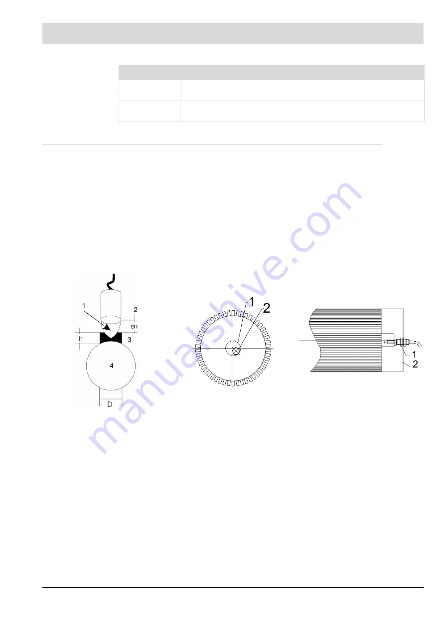
The illustration (left) shows a typical arrangement of attenuating element, sensor and shaft.
How the system works:
Every inductive sensor forms an electric field at its active surface, from which the contact gap
(nominal contact gap "Sn”) can be derived as a function of sensor size. The table lists several
typical sensors with their characteristics. The effective contact gap is 0.8 x nominal contact
gap in the case of structural steel. An additional correction factor that depends on the material
must be included for other materials. These factors are specified in the sensor manufacturer's
data-sheets.
The installation distance between the sensor and the attenuating element's upper edge should
be Sn/2 (half the nominal contact gap). The sensor's diameter depends on the required nom-
Type No.
Description
660 R 8101
r.p.m. sensor as a two wire system
d= 12mm, switch gab 2mm
663 R 8103
inductive sensor with switch terminals in three wire system
d=12mm, switch gab 4mm
Fig. 9-24 typical arrangement of attenua-
ting element, sensor and shaft.
Fig. 9-25 face
Fig. 9-26 side
1 = field
2 = sensor
3 = attentuating element
4 = shaft
1 = motor shaft
30
2 = M8 screw head glued or bolted
1 = 2xM12 bolted
2 = original cowling for the cooling
vane of separate locking frame.
Summary of Contents for ETAMATIC
Page 1: ...Manual ETAMATIC ETAMATIC S CE 0085 AU 0207 Sensors and Systems for Combustion Engineering...
Page 2: ......
Page 7: ...6 Table of Contents 9 27 Dimensions and weight 128 9 28 Declaration of Conformity 131...
Page 65: ...64 8 Control Mode 8 2 1 Leakage test flow chart Fig 8 4 Flow chart leakage test...
Page 90: ...89 9 Appendix 9 8 Process Sequence Charts Fig 9 3 Process sequence chart gas with pilot burner...
Page 91: ...90 9 Appendix Fig 9 4 Process sequence chart oil with pilot burner...
Page 92: ...91 9 Appendix Fig 9 5 Process sequence chart gas without pilot burner...
Page 93: ...92 9 Appendix Fig 9 6 Process sequence chart oil without pilot burner...
Page 99: ...98 9 Appendix Fig 9 8 ETAMATIC S wiring diagram with ignition flame monitoring...
Page 104: ...103 9 Appendix Fig 9 16 LSB connection ETAMATIC LT1 other LAMTEC devices...
Page 134: ...133 9 Appendix...
Page 135: ......