


192
8
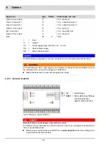
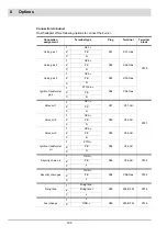
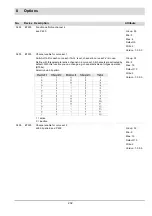
Options
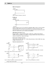
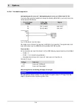
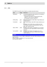
8.2.3.2 Terminal Assignment
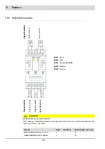
Acknowledgement curve set 1 /Acknowledgement curve set 2 (Terminals 36; 34)
To provide that signal ’fuel selection’ is clearly identified by BT340/341, you must connect ter-
minals as described below:
The inputs load+ and load- are reserved on BT300 by fuel selection. The signals load+ and
load- will be taken over by DFM300 and transmitted to BT300 by LSB.
Fuel selection
For fuel selection via input of terminal 13 of the DFM following requirements must be fulfilled:
–
P 0812 = 1
–
P 0801 = 3 or 4 (dual fuel applications)
–
all parameters and curve for curve set 1 and curve set 2 must be set.
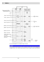
Terminal 13 circuit:
Circuit diagram for modulating 2/3 stage oil and gas
NOTICE
The gas ignition valve is optional. You can replace oil ignition valve for 3
rd
stage from two-
stage oil operation with an optional ignition valve.
From terminal
DFM300
to the plug
X09 BT300
Signal
34
Pin 1 (Load-)
curve set 2
36
Pin 2 (Load+)
curve set 1
Fig. 8-29 Feedback connection oil/gas
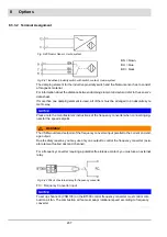
Voltage
Curve set
0 V
Curve set 1 (Oil/Gas1)
230 V
Curve set 2 (Gas/Gas2)
Summary of Contents for BT300 BurnerTronic
Page 2: ......
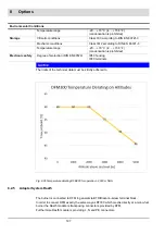
Page 25: ...24 3 Product Description Fig 3 9 Temperature derating BT300 for operation 2000 m NHN...
Page 49: ...48 4 Design and Functions Fig 4 20 Oil with pilot burner BT300...
Page 50: ...49 4 Design and Functions Fig 4 21 Oil without pilot burner BT300...
Page 51: ...50 4 Design and Functions Fig 4 22 Gas with pilot burner and leakage test BT300...
Page 52: ...51 4 Design and Functions Fig 4 23 Gas without pilot burner and leakage test BT300...
Page 53: ...52 4 Design and Functions Fig 4 24 Oil without pilot burner BT335...
Page 54: ...53 4 Design and Functions Fig 4 25 Gas without pilot burner and leakage test BT335...
Page 59: ...58 4 Design and Functions Fig 4 28 Leakage test process diagram...
Page 98: ...97 6 Operating Control and Displays...
Page 99: ...98 6 Operating Control and Displays...
Page 103: ...102 6 Operating Control and Displays...
Page 105: ...104 6 Operating Control and Displays...
Page 106: ...105 6 Operating Control and Displays...
Page 107: ...106 6 Operating Control and Displays...
Page 109: ...108 6 Operating Control and Displays...
Page 126: ...125 6 Operating Control and Displays 6 3 4 2 Curve Table Fig 6 37 Curve table window...
Page 246: ...242 10 EU Declaration of Conformity 10 EU Declaration of Conformity...
Page 247: ...243 10 EU Declaration of Conformity...


