


176
8
Options
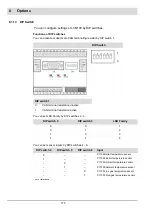
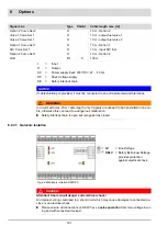
8.1.15 Electrical Connection
Connect power control unit module LCM100 to BT300 via plug X31 and LCM terminals 10 -
13. The cable type 667P0515 can be used for this purpose.
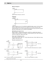
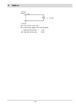
Valid for BT300 version 1.x.x.x
: As soon as an LCM100 is connected to BT300, the inputs
Firing rate- and Firing rate+ will no longer be supported by the plug X09. It is very important
to connect these signals as potential-free contacts to the LCM100 (see chapter
8.1.15.2 Ter-
minal Assignment
).
LED
Colour
Relevance
ERR
(LED 1)
red
During normal operation this LED is switched off. It will light
up under following conditions:
- Initialisation not yet accomplished or aborted
(e.g. HW could not be initialised)
- Cannot receive any messages for at least 3 seconds
CAN
(LED 2)
green
OFF:
CAN Controller in Bus OFF. No communication possi-
ble.
Blinking:
CAN Controller discovered a temporary fault.
After fixing the problem, LED would still blink for some time.
ON:
CAN is ready to operate.
PWR
(LED 3)
green
ON:
Module is working normally = fully initialised and with-
out any fault.
8.1.14 LEDs
The LCM100 has 3 LEDs which should be connected as mentioned below:
Summary of Contents for BT300 BurnerTronic
Page 2: ......
Page 25: ...24 3 Product Description Fig 3 9 Temperature derating BT300 for operation 2000 m NHN...
Page 49: ...48 4 Design and Functions Fig 4 20 Oil with pilot burner BT300...
Page 50: ...49 4 Design and Functions Fig 4 21 Oil without pilot burner BT300...
Page 51: ...50 4 Design and Functions Fig 4 22 Gas with pilot burner and leakage test BT300...
Page 52: ...51 4 Design and Functions Fig 4 23 Gas without pilot burner and leakage test BT300...
Page 53: ...52 4 Design and Functions Fig 4 24 Oil without pilot burner BT335...
Page 54: ...53 4 Design and Functions Fig 4 25 Gas without pilot burner and leakage test BT335...
Page 59: ...58 4 Design and Functions Fig 4 28 Leakage test process diagram...
Page 98: ...97 6 Operating Control and Displays...
Page 99: ...98 6 Operating Control and Displays...
Page 103: ...102 6 Operating Control and Displays...
Page 105: ...104 6 Operating Control and Displays...
Page 106: ...105 6 Operating Control and Displays...
Page 107: ...106 6 Operating Control and Displays...
Page 109: ...108 6 Operating Control and Displays...
Page 126: ...125 6 Operating Control and Displays 6 3 4 2 Curve Table Fig 6 37 Curve table window...
Page 246: ...242 10 EU Declaration of Conformity 10 EU Declaration of Conformity...
Page 247: ...243 10 EU Declaration of Conformity...


