21
21
EN
DE
20
20
DE
EN
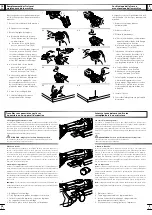
Zeta P2 Akku
Einsatz für P-System
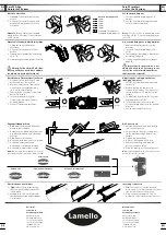
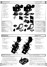
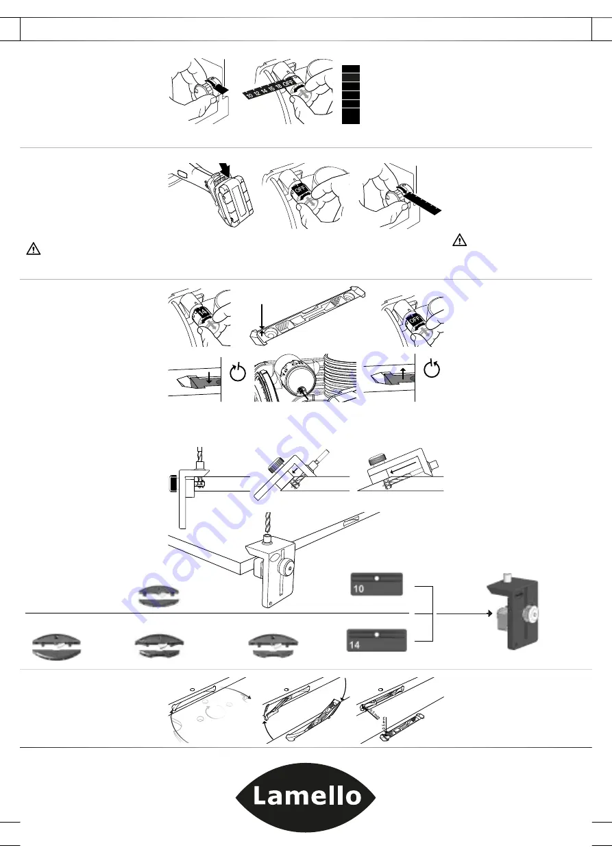
Frästiefe einstellen
1 Standard-Tiefensteller auf «max»
stellen
2 P-System-Tiefensteller ziehen und
drehen und auf gewünschte Tiefe
einstellen
Hinweis:
Für den Einsatz als Standard-
maschine den P-System Tiefensteller auf
«OFF» stellen
Einsatz als Standard-Nutfräsmaschine
1 Akkupack von der Maschine
entfernen
2 P-System Tiefensteller auf «OFF»
drehen
3 Fräserwechsel gemäss Beschreibung
Seite 16
4 Schattenfugen fräsen gemäss Seite 19
Wichtig: Falls nicht mit Profi l-Nut-
fräser gearbeitet wird, darf Hubme-
chanik nie eingeschaltet werden!
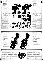
Frästiefe nach Fräserwechsel justieren
1 P-System-Tiefensteller ziehen und
drehen und auf 14 einstellen
2 Muster einfräsen und Clamex P-14
einschieben, der Verbinder muss
ca. 0.5 mm zurückstehen
3 Zum Justieren P-System-Tiefensteller
auf «OFF» drehen
4 Justierschraube im P-System-
Tiefensteller in die gewünschte
Richtung drehen
5 Erneute Testfräsung ausführen
Zeta P2 cordless
use for the P-System
Set the depth adjuster
1 Set the standard depth adjuster to
«max»
2 Pull the P-System depth adjuster and
turn to the desired depth
Note:
For the use as a standard biscuit
machine set the P-System depth adjuster
to «OFF»
Use as a standard groove cutting machine
1 Remove the battery pack from the
machine
2 Set the P-System depth adjuster to
«OFF»
3 Cutter change according to description
according to page 16
4 Cutting expansion gaps according to
page 19
Important: if the machine is not
equipped with the P-System groove
cutter, the vertical mechanical drive
shall never be released!
Adjusting the cutting depth after
changing the cutter
1 Pull the P-System depth adjuster and
turn to 14
2 Make a sample cut and insert a
Clamex P-14 element. The connector
should be approx. 0.5 mm below the
surface
3 To adjust the depth turn the P-System
depth adjuster to «OFF»
4 Turn the adjustment screw in the
P-System depth adjuster in the desired
direction
5 Cut another sample to check
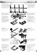
Zugangsöffnung bohren
1 Rändelmutter lösen und Bohrlehre
mittig in Nut schieben
2 Darauf achten, dass die Bohrlehre auf
der Werkstückkante und -fl äche gut
aufl iegt.
3 Rändelmutter festziehen
4 Bohrlehre festhalten und Loch bohren
5 Bohrlehre herausziehen und
Ausfräsung von Spänen reinigen
6 Bohrlehre in nächste Nut stecken
Hinweis:
Nur Spiralbohrer Ø 6 mm mit Zentrier-
spitze und Doppelfase verwenden! (Art. Nr. 131506)
Drill access hole
1 Release knurled nut and push drill jig
into centre of groove
2 Ensure that the drill jig is resting well
on the workpiece edge and on the
surface
3 Tighten the knurled nut
4 Hold the drill jig and drill a hole
5 Remove the drill jig and clean the
groove to remove chips
6 Place the drill jig into the next groove
Note:
Spiral drill Ø 6 mm with centering point and
double heel (Art. No. 131506)
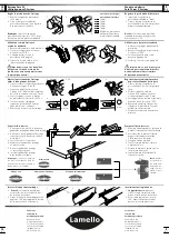
Einschieben von Verbinder
1
Tipp:
In der Fräser-Drehrichtung
lässt sich der Verbinder einfacher
einschieben
2 Verbinder ca 100° zur Werkstück-
ober fl äche ansetzen und Verbinder
einschieben
Inserting connectors
1
Tip:
The connector can be inserted
more easily if it is inserted from the same
side as the cutter cut the groove
2 Place connector at approx. 100° to
workpiece surface and insert connector
Hersteller:
Lamello AG
Verbindungstechnik
Hauptstrasse 149
CH-4416 Bubendorf
Tel. +41 61 935 36 36
Fax +41 61 935 36 06
[email protected]
www.lamello.com
Manufacturer:
Lamello AG
Verbindungstechnik
Hauptstrasse 149
CH-4416 Bubendorf
Tel. +41 61 935 36 36
Fax +41 61 935 36 06
[email protected]
www.lamello.com
0.5
mm
max
0 10 20 S D max
+ 0.7 mm
1 ×
- 0.7 mm
1 ×
Frästiefe | Cutting depth
10
10 mm
12
12 mm
14
14 mm
15
15 mm
18
18 mm
OFF
Standard-Tiefensteller /
Standard depth adjuster
1
1
4
2
2
1
2 + 5
3
Clamex P-10
Clamex P-14/10 Flexus
Clamex P-14
Clamex P-14/10 Medius
0.5
mm
0.
5
mm
1
2


