


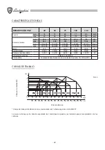


- 34
-
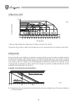
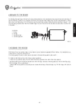
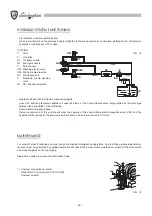
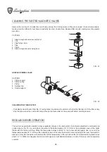
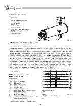
HYDRAULIC SYSTEM FUNCTIONING
- Pre-ventilation and pre-ignition phase:
the burner will start and the previously heated naphtha in the pre-heater tank can circulate, yielding heat to the burner’s
hydraulic circuit because VE1 is open.
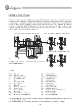
CAPTION
C Tank
F Line
filter
G1 1st-flame
nozzle
G2 2nd-flame
nozzle
P Burner
pump
VE1 Washing electro-valve
VE2 2nd flame electro-valve
SP Pre-heater
tank
V Mechanic
nozzle
opening
valve
R1 VE1 heating resistance
- Operation phase with first flame at reduced capacity:
close VE1 and the pressured naphtha will open the piston of the nozzle closure valve, being ignited by the discharge
between the extremities of the electrodes;
- Second flame operation phase:
the servo command of the air gate will order the opening of the second-flame electro-magnetic valve (VE2) and the
naphtha will be ignited by the previously existent flame. The burner will work in full force.
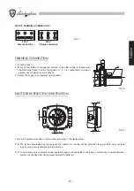
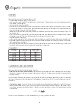
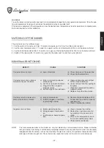
MAINTENANCE
For correct burner functioning you must carry out periodical maintenance operations. Some of these (extraordinary main-
tenance) must be performed by qualified personnel. Whenever the burner must be worked on, switch off the main switch
and close the gates on the fuel piping.
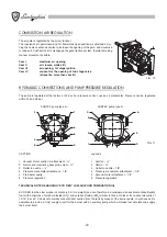
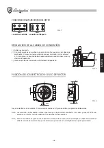
Operations needed to access the carburetion head:
1) Unscrew connections A and B.
Slide off pin C (for models 50-75-100-130).
Unscrew screw D.
G1
G2
R2
R1
VE1
R3
V
V
VE2
R4
SP
P
C
F
C
B
A
D
FIG. 14
FIG. 15