


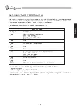


- 31
-
ENGLISH
IGNITION
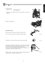
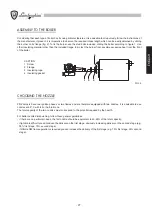
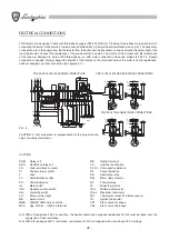
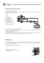
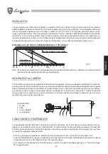
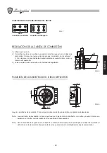
Make sure the main switch is inserted (fig. 6 pos. IG):
- set the switchboard switch (fig. 6 pos. Ima) at “off”;
- insert fuel in the suction flexible. This operation is not necessary for “falling” systems, but can be particularly useful to
prime pumps in suction plants;
- tie the suction flexible to the line filter;
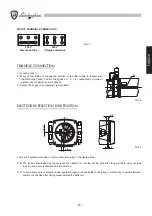
- open the cover of the switchboard and use a screwdriver to adjust the mobile parts of the motor relay (fig. 6 pos. RM).
The motor will start and so will the pump, which will initiate plant loading. This operation will be concluded when fuel
without air bubbles comes out of the return flexible;
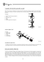
- release the mobile parts of the motor relay. Assemble the manometer and the vacuum meter on the pump (see fig. 11 for
the attachments);
- work on the motor relay mobile parts again to fill the pre-heater tank. This operation will be concluded when fuel without
air bubbles comes out of the return flexible; release the mobile parts of the motor relay;
- tie the flexible around its piping;
- set the switchboard switch at “on” and make sure the thermostat line is closed: the burner will then start automatically. For
PN models naphtha will start heating; when the minimum thermostat calibration level of the pre-heater tank is reached,
the burner will start automatically;
- make sure the pressure in the pump is within 22 and 26 atm and that vacuum does not exceed 6 mH
2
O. Remove the
manometer and the vacuum meter and place their relative taps on the pumps.
CONSUMPTION
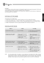
CALIBRATION AND ADJUSTMENT
Make sure the main switch is inserted (see fig. 6 pos. IG):
-
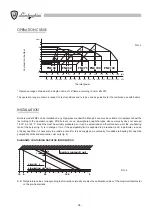
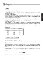
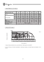
Calibration of pre-heater tank thermostats:
the temperature the naphtha must reach is determined by the maximum
thermostat, in relation to viscosity, according to the diagram on figure 4. This temperature should be measured while the
burner is working.
Use the minimum thermostat incorporated to the pre-heater (as well as the maximum thermostat; see fig. 12) to establish
the minimum temperature for burner operation. This temperature is fixed at about 20-30° C below the maximum, and never
below 70° C.
-
Combustion analysis:
the correct amount of air for combustion is determined by analysing fumes with CO
2
% measu-
rement (recommended value: 11-13%), fume temperature, room temperature and fume opacity or BH number. These
controls must be carried out while the boiler is in function, i.e. some time after a cold start. Yield is calculated according
to this formula:
where Tf = fume temperature; Ta = room temperature; CO
2
% = CO
2
contents in the fumes.
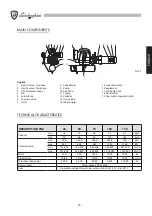
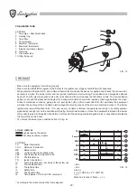
BURNER
MOTOR
RESISTANCE
W
tank W
PNZ 30
370
1800
PNZ 50
740
4500
PNZ 75
1500
6000
PNZ 100
1500
7800
PNZ 130
1800
9800
n = 100 - 0,65 Tf - Ta
CO
2
%