


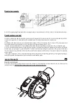


REGULATIONS
Combustion head shutter regulation LO 700
Ex. If the burner should operate at 500kW with a counterpressure of 3 mbar, the air ring must be positioned in
correspondence with mark 3 on rod T (Fig. 4)
0,00
1,00
2,00
3,00
4,00
5,00
6,00
7,00
50
100
150
200
250
300
350
400
450
500
kW
550
600
650
700
max
3
2
min
1
It is necessary
to position the air ring (Diagram A) in the desired working point referring to diagram A. Based on
the working point of the burner (supplied power / pressure in combustion chamber) a position is indicated (min -
1 - 2 - 3 - max) for the air adjustment ring which corresponds with the marks on rod T (Fig. 4).
M U
Diagram A
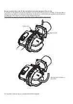
0,00
1,00
2,00
3,00
4,00
5,00
6,00
7,00
8,00
mbar
0
100
200
300
400
500
600
700
800
900
1000 kW
max
3
2
min
1
Diagram A
Combustion head shutter regulation LO 1000
Ex. If the burner should operate at 600kW with a counterpressure of 4 mbar, the air ring must be positioned in
correspondence with mark 2 on rod T (Fig. 4)