background image

SDC-EC15N 

Hardware Integration Guide 

Embedded Wireless Solutions Support Center:   
http://ews-support.lairdtech.com 

www.lairdtech.com/bluetooth


13 

© Copyright 2015 Laird. All Rights Reserved


Americas: +1-800-492-2320 

Europe: +44-1628-858-940 

Hong Kong: +852 2923 0600


interference will not occur in a particular installation. If this equipment does cause harmful 
interference to radio or television reception, which can be determined by turning the equipment 
off and on, the user is encouraged to try to correct the interference by one of the following 
measures:   

1.


Reorient or relocate the receiving antenna. 

2.


Increase the separation between the equipment and receiver. 

3.


Connect the equipment into an outlet on a circuit different from that to which the receiver 
is connected. 

4.


Consult the dealer or an experienced radio/TV technician for help.   


FCC Caution: Any changes or modifications not expressly approved by the party responsible for 
compliance could void the user's authority to operate this equipment. 


This device complies with Part 15 of the FCC Rules. Operation is subject to the following two 
conditions: (1) This device may not cause harmful interference, and (2) this device must accept any 
interference received, including interference that may cause undesired operation. 


IMPORTANT NOTE: FCC Radiation Exposure Statement:   

This equipment complies with FCC radiation exposure limits set forth for an uncontrolled 
environment. This equipment should be installed and operated with minimum distance 20cm 
between the radiator & your body.   


Industry Canada   

User’s Guide Requirements 

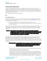
As outlined in the Operational Description, the SDC-EC15N complies with Industry Canada (IC) rules for a 
Limited Modular Approval. To leverage Laird’s grant, the two conditions below must be met for the host 
device into which the SDC-EC15N is integrated:   

1.


The antenna is installed with 20 cm maintained between the antenna and users.   

2.


The transmitter module is not co-located with any other transmitter or antenna that is capable of 
simultaneous operation.   

As long as the two conditions above are met, further 

transmitter

 testing is typically not required. However, the 

OEM integrator is still responsible for testing its end-product for any additional compliance requirements 
required with this module installed, such as (but not limited to) digital device emissions and PC peripheral 
requirements. 

Important!   In the event that the two conditions above 

cannot be met 

(for example certain device 

configurations or co-location with another transmitter), then the IC authorization is no longer 
considered valid and the IC ID 

cannot

 be used on the final product. In these circumstances, the 

OEM integrator will be responsible for re-evaluating the end product (including the transmitter) 
and obtaining a separate IC authorization. 

Summary of Contents for SDC-EC15N

Page 1: ...Americas 1 800 492 2320 Option 2 Europe 44 1628 858 940 Hong Kong 852 2923 0600 www lairdtech com wi fi SDC EC15N Hardware Integration Guide Version 2 0 ...

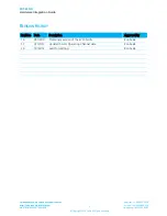
Page 2: ...tooth 2 Copyright 2015 Laird All Rights Reserved Americas 1 800 492 2320 Europe 44 1628 858 940 Hong Kong 852 2923 0600 REVISION HISTORY Revision Date Description Approved By 1 0 05 10 10 Preliminary version of the EC15N HIG Ron Seide 1 1 01 31 13 Updated 5 GHz Operating Channel data Ron Seide 2 0 10 22 13 Laird Formatting Ron Seide ...

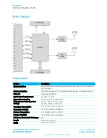
Page 3: ...Europe 44 1628 858 940 Hong Kong 852 2923 0600 CONTENTS Revision History 1 Scope 4 Operational Description 4 Block Diagram 5 Specifications 5 Pin Definitions and Interface Notes 9 Pin Definitions 9 Interface Notes 10 Mechanical Specifications 10 Connector Overview 10 RF Layout Design Guidelines 10 Regulatory 11 Certified Antennas 11 Documentation Requirements 12 FCC 12 Industry Canada 13 European ...

Page 4: ...e network infrastructure the SDC EC15N conforms to commands from the infrastructure for radar avoidance The SDC EC15N is compliant with 32 bit PCIe Express Card mechanical specifications and interfaces to host devices via a 26 pin connector The device is based on the Broadcom BCM4322 chip which is an 802 n compliant integrated device providing a Media Access Controller MAC a Physical Layer Control...

Page 5: ...xpress PCIe Card with 26 pin connector Antenna Interface 2 MMCX connectors for dual band diversity and 2 x 2 MIMO support Chip Set Broadcom BCM4322 Input Power Requirements 3 3 VDC 10 Current Consumption At maximum transmit power setting Transmit 600 mA 1980 mW Receive 450 mA 1485 mW Standby TBD mA TBD mW Operating Temperature 30 to 75 C 22 to 167 F Operating Humidity 10 to 90 non condensing Stora...

Page 6: ...8 87 116 130 144 802 11n OFDM 40 MHz channels 30 60 90 120 180 240 270 300 Modulation BPSK 1 6 9 14 30 Mbps QPSK 2 12 18 29 43 60 90 Mbps CCK 5 5 11 Mbps 16 QAM 24 36 58 87 120 180 Mbps 64 QAM 48 54 116 130 144 240 270 300 Mbps Modulation and Coding Scheme MCS Index Values Supported 0 15 Regulatory Domain Support FCC Americas Parts of Asia and Middle East ETSI Europe Middle East Africa and Parts o...

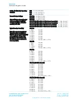
Page 7: ...02 11n 40 MHz wide 5 GHz channel operation 14 dBm 25 mW Typical Receiver Sensitivity Note We cannot currently test Typical Receiver Sensitivity for 802 11n due to lack of availability of an applicable AP one that functions in Greenfield mode We will have these numbers as soon as possible 802 11a 6 Mbps 85 dBm 12 Mbps 83 dBm 18 Mbps 80 dBm 24 Mbps 76 dBm 36 Mbps 73 dBm 48 Mbps 70 dBm 54 Mbps 65 dBm...

Page 8: ...WEP RC4 Algorithm Temporal Key Integrity Protocol TKIP RC4 Algorithm Advanced Encryption Standard AES Rijndael Algorithm Encryption Key Provisioning Static 40 bit and 128 bit lengths Pre Shared PSK Dynamic 802 1X Extensible Authentication Protocol Types EAP FAST EAP TLS EAP TTLS PEAP TLS PEAP GTC PEAP MSCHAPv2 LEAP Operating Systems Supported Windows XP Professional and Embedded Compliance ETSI Re...

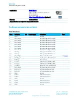
Page 9: ...3 No Connect Not Used Leave Open Float 4 No Connect Not Used Leave Open Float 5 No Connect Not Used Leave Open Float 6 No Connect Not Used Leave Open Float 7 No Connect Not Used Leave Open Float 8 No Connect Not Used Leave Open Float 9 VCC1_5 Primary 1 5 V Module Power 10 VCC1_5 Primary 1 5 V Module Power 11 WL_GPIO_1 Wake on Wireless LAN See Pin 11 12 VAUX_3_3 Auxiliary 3 3 V Module Power 13 PERS...

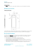
Page 10: ...dditional mounting hardware RF LAYOUT DESIGN GUIDELINES The following is a list of RF layout design guidelines and recommendation when installing a Summit brand radio into your device Please note that because each device is different Laird cannot approve and or guarantee the outcome of your specific design Do not run antenna cables directly above or directly below the radio Do not place any parts ...

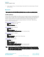
Page 11: ...as been tested to the same regulatory standards as the SDC PE15N These tests were conducted with the following antennas Summit SDC CF22G Antenna click for datasheet Form Factor Chip Antenna on PCB Type Dipole Maximum 2 4 GHz Gain 0 dBi Cisco AIR ANT 4941 click for datasheet Form Factor Whip Type Dipole Maximum 2 4 GHz Gain 2 2 dBi Tested and Certified 2 4 GHz Transmit Power 90 of maximum setting R...

Page 12: ...ements Important In the event that the two conditions above cannot be met for example certain device configurations or co location with another transmitter then the FCC authorization is no longer considered valid and the FCC ID cannot be used on the final product In these circumstances the OEM integrator will be responsible for re evaluating the end product including the transmitter and obtaining ...

Page 13: ...ation Exposure Statement This equipment complies with FCC radiation exposure limits set forth for an uncontrolled environment This equipment should be installed and operated with minimum distance 20cm between the radiator your body Industry Canada User s Guide Requirements As outlined in the Operational Description the SDC EC15N complies with Industry Canada IC rules for a Limited Modular Approval...

Page 14: ...nformation for each antenna used with the host device into which the SDC EC15N is integrated The following examples are based on the integrated antenna with which the SDC EC15N was certified and represent an acceptable format Summit SDC CF22G Antenna click for datasheet Form Factor Chip Antenna on PCB Type Dipole Maximum 2 4 GHz Gain 0 dBi Cisco AIR ANT 4941 click for datasheet Form Factor Whip Ty...

Page 15: ...atters ERM Broadband Radio Access Networks BRAN Specific conditions for 5 GHz high performance RLAN equipment EU 2002 95 EC RoHS Declaration of Compliance EU Directive 2003 95 EC Reduction of Hazardous Substances RoHS This device is a 2 4 GHz wideband transmission system transceiver intended for use in all EU member states and EFTA countries except in France and Italy where restrictive use applies...

Page 16: ...aux autres dispositions pertinentes de la directive 1999 5 CE Italiano Italian Con la presente nome del costruttore dichiara che questo tipo di apparecchio è conforme ai requisiti essenziali ed alle altre disposizioni pertinenti stabilite dalla direttiva 1999 5 CE Latviski Latvian Ar šo name of manufacturer izgatavotāja nosaukums deklarē ka type of equipment iekārtas tips atbilst Direktīvas 1999 5...

Page 17: ...9 5 CE Slovensko Slovenian Ime proizvajalca izjavlja da je ta tip opreme v skladu z bistvenimi zahtevami in ostalimi relevantnimi določili direktive 1999 5 ES Slovensky Slovak Meno výrobcu týmto vyhlasuje že typ zariadenia spĺňa základné požiadavky a všetky príslušné ustanovenia Smernice 1999 5 ES Suomi Finnish Valmistaja manufacturer vakuuttaa täten että type of equipment laitteen tyyppimerkintä ...

Reviews: