Laird MSD45N
Hardware Integration Guide, version 1.1
Embedded Wireless Solutions Support Center:
http://ews-support.lairdtech.com
www.lairdtech.com/wireless
5
Laird Technologies
Americas: +1-800-492-2320 Option 2
Europe: +44-1628-858-940
Hong Kong: +852-2268-6567 x026
B
LOCK
D
IAGRAM
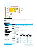
Figure 1: MSD45 Block Diagram
Note: Transmitter frequencies for Wi-Fi are 2412-2462 MHz and 5180-5805 MHz.
S
PECIFICATIONS
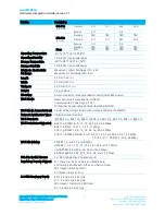
Table 1: Specifications
Feature
Description
Physical Interface
Molex 54722-0607 60-pin connector (mates to Molex 55560-0607 60-pin
connector)
Wi-Fi Interface
1-bit or 4-bit Secure Digital I/O
Note: Can support 1.8 V or 3.3 V depending on the supply voltage on VDDIO
(pin-21).
Antenna Interface
1 Hirose U.FL connector
Main Chip
Qualcomm Atheros AR6003 single-chip client
Input Voltage Requirements 3.3 VDC ± 5% (core)
I/O Signalling Voltage
3.3 VDC ± 5%
1.8 VDC ± 5%
Average Current
Consumption
(At maximum transmit
power setting)
Note:
Standby refers to the
radio operating in PM1
powersave mode.
Mode
1.8 V
3.3 V
Avg.
Current
Max.
Current
Avg.
Current
(mA)
Max.
Current
(mA)
802.11a
Transmit
0.11
0.11
496
500
Receive
0.11
-
0.2
-
Standby
TBD
TBD
TBD
TBD
802.11b
Transmit
0.11
0.11
380
420
Receive
0.11
-
0.2
-
Standby
TBD
TBD
TBD
TBD
802.11g
Transmit
0.11
0.11
355
410
Receive
0.11
-
0.2
-
Standby
TBD
TBD
TBD
TBD


