


www..lairdconnect.com/wireless
5
© Copyright 2020 Laird Connectivity. All Rights Reserved
Americas
: +1-800-492-2320
Europe
: +44-1628-858-940
Hong Kong
: +852 2923 0610
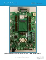
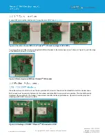
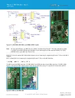
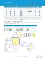
This section describes the Pinnacle
™ 100 development board hardware. The Pinnacle™ 100 development board is delivered
with the Pinnacle
™ 100 series modem loaded with Zephyr Out of Box (OOB) example code.
The Pinnacle
™ 100 development board is a universal development tool that highlights the capabilities of the Pinnacle™ 100
modem. The development kit is supplied in a default configuration which should be suitable for multiple experimentation
options. It also offers several header connectors that help isolate on-board sensors and UART from the Pinnacle
™ 100
modem to create different configurations. This allows you to test different operating scenarios.
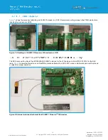
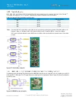
The board allows the Pinnacle
™ 100 series modem to physically connect to a PC via the supplied USB cable for development
purposes. The development board provides USB-to-Virtual COM port conversion through a FTDI chip
– part number FT232R.
Any Windows PC (XP or later) should auto-install the necessary drivers; if your PC cannot locate the drivers, you can
download them from
http://www.ftdichip.com/Drivers/VCP.htm
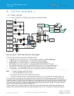
The
Pinnacle™ 100 development board has the following features:
▪
M.2, KEY E, PCI connector to connect a Pinnacle
™ 100 series modem into the development board
▪
The following power supply options for powering the development board:
–
USB (micro-USB, type B)
–
External DC supply (4.4-12V)
– supplied. Center positive barrel connector or header for bench supply.
–
(4) AA batteries
– not supplied. Assume Lithium Iron Disulfide (4.4 – 7.2V)
–
(2) AA batteries
– not supplied. Assume Lithium Iron Disulfide (2.2 – 3.6V)
▪
When powering the DVK with USB, Ext DC, or 4 AA, a DC-DC converter is used to supply the DVK with 3.7V. The DVK
also includes regulated 1.8V and a regulated 3.3V.
▪
When powering with 2AA, the DC-DC converter is bypassed, as well as the regulated 3.3V
▪
Placing a coin-cell (CR2032) in J13, provides a backup power supply to HL7800 RTC. (Not currently supported)
▪
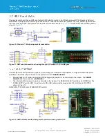
USB FTDI (J30) to UART bridge (FTDI chip)
▪
Pinnacle
™ 100 UART can be interfaced to:
–
USB FTDI using the USB-UART bridge (FTDI chip)
–
An external UART using J12.
▪
Pinnacle
™ 100 modem only current measuring option:
–
J4 Pin header (ammeter)
▪
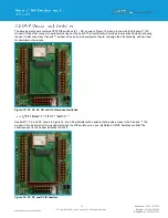
IO break-out 2.54-mm pitch pin header connectors that bring out all interfaces of the Pinnacle
™ 100 modem – UART,
SPI, I2C, SIO [DIO or AIN (ADCs)], NFC
– and allows for plugging in external modules/sensors.
▪
DIP switches on all Pinnacle
TM
modem IO lines running to peripheral devices on the development board to allow
disconnection.
▪
On-board Bosch Sensortec BME680 environmental sensor
▪
Four buttons and four LEDs for user interaction
▪
One reset button
▪
NFC antenna connector on-board development board for use with supplied flexi-PCB NFC antenna
▪
Debug and program NRF software using both an internal and an external serial wire debug (SWD)or trace interface
▪
GPS antenna
▪
Optional
footprint for Microchip ATECC608A-SSHDA authentication IC (not populated)
▪
Optional Spare Level Shifter
Summary of Contents for 453-00010-K1
Page 1: ...Version 1 0 ...


