


30
General Cleanliness
Chassis Daily Cleaning
To clean the chassis, do the following:
1.
Make sure that there is enough clearance above the body to raise it safely.
2.
Start the truck’s engine.
3.
Turn ON the pump switch.
4.
Raise the body until the safety prop is free to tilt under it.
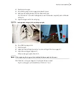
5.
Release the safety prop using the safety prop handle (Figure 2
3) and position it adequately.
6.
Lower the body until it rests on the safety prop.
7.
Turn OFF the pump switch.
8.
Stop the engine.
9.
Lock out and tag out the vehicle (see
Figure 3
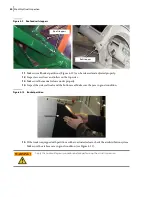
-
2 Body Safety Prop
Be careful not to use pressurized water on cylinder heads, joints or electrical devices such
as limit/proximity switches.
Apply the Lockout/Tagout procedure to prevent accidental/unintentional/unauthorized
engine start-up.
WARNING!
WARNING!
Summary of Contents for Top Select
Page 1: ...TOP SELECT TM MAINTENANCE MANUAL...
Page 2: ......
Page 3: ...TOP SELECT MAINTENANCE MANUAL...
Page 8: ...vi Table of Contents...
Page 34: ...26 Safety...
Page 40: ...32 General Cleanliness...
Page 72: ...64 Loading Container Maintenance...
Page 104: ...96 Preventive Maintenance...
Page 121: ...Lubrication 113 Figure 11 2 Body hinges Grease Fittings on Body Figure 11 3 Tailgate and hooks...
Page 122: ...114 Lubrication Figure 11 4 Partition Figure 11 5 Optional Maximizer Location of lube zerks...
Page 123: ...Lubrication 115 Figure 11 6 Roof hinges and loading cylinders...
Page 124: ...116 Lubrication Figure 11 7 Lube chart...
Page 132: ...124 Troubleshooting...
Page 134: ...126 Hydraulic and Pneumatic Circuit Diagrams Hydraulic Schematics Single Side Bucket...
Page 135: ...Hydraulic and Pneumatic Circuit Diagrams 127 Single Side Bucket w Maximizer...
Page 136: ...128 Hydraulic and Pneumatic Circuit Diagrams Dual Side Bucket...
Page 137: ...Hydraulic and Pneumatic Circuit Diagrams 129 Dual Side Bucket w Maximizer...
Page 139: ...Hydraulic and Pneumatic Circuit Diagrams 131 Air System Schematics TS 1000 w Options...
Page 140: ...132 Hydraulic and Pneumatic Circuit Diagrams TS 2000 w Options...