background image

Safety

21

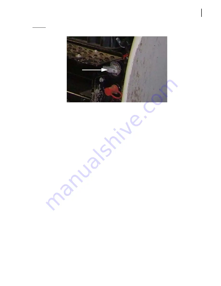
Figure 2-16      Master switch

7.

Put an “O

FF 

S

ERVICE

” tag on the driver’s wheel and on the front windshield.

8.

Use safety props to block any system that could move by gravity (open tailgate, etc.).

9.

Drain all air tanks.

Verify and inspect any security device and/or mechanism to make sure that there is no bypass and 
that they are all functional.

Shutting Down the Vehicle

If the vehicle has to be stored for an extended period of time, follow the chassis manufacturer’s 
shutdown and maintenance requirements.

Also:

1.

Park the vehicle on hard level ground, and apply the parking brake.

2.

Make sure that all moving parts are in their home position (tailgate, arm, crusher panel, packer, 
etc.).

3.

Turn off, in sequence, the hydraulic pump, the electrical system, the engine and the master 
switch.

4.

Drain all air tanks (see Figure 2-17).

Summary of Contents for MINIMAX

Page 1: ...MINIMAX TM MAINTENANCE MANUAL...

Page 2: ......

Page 3: ...MINIMAX MAINTENANCE MANUAL...

Page 4: ...on contained in this document All risks and damages incidental or otherwise arising from the use or misuse of the information contained herein are entirely the responsability of the user Although care...

Page 5: ...s Responsibilities 7 Things to Do 7 Things to Avoid 7 General Precautions 8 Welding 10 Fire 10 Safety Kits 11 Safety Features 11 Global Motion Sensors Optional 11 Back Up Alarm 13 Tailgate Safety Prop...

Page 6: ...ing to Take a Sample 58 Taking an Oil Sample 59 Lubrication Charts 62 Greasing the Crusher Panel 65 Tailgate 66 Greasing Tailgate Hinges Locking Mechanism and Cylinder Pins 66 Packer 68 Cylinder Pins...

Page 7: ...ation 124 Tailgate Locking Mechanism 125 Tailgate Unlocking Spontaneously 127 Tailgate Lowering Spontaneously 128 Multiplexing 129 Labrie s Multiplexed System 129 Cart Counter optional 130 Warning and...

Page 8: ...vi Table of Contents Adjusting Arm Speed 164...

Page 9: ...nance of the chassis This is dealt in the chassis manufacturer s service manual Cameras and backing accident prevention systems For these options refer to the appropriate manufacturer s service manual...

Page 10: ...g out movement The MINIMAX is composed of a small curved wall body with a capacity of 10 cubic yards and a 2 cubic yard tailgate making the total loading capacity of the vehicle to be 12 cubic yards T...

Page 11: ...re the lubrication points are located on the vehicle and how often the parts should be lubricated Initial lubrication carried out by Labrie Enviroquip Group is sufficient for production and transport...

Page 12: ...2T3 Toll Free 1 877 831 8250 Telephone 1 418 831 8250 Service Fax 1 418 831 1673 Parts Fax 1 418 831 7561 Parts and warranty During business hours 8 00 AM to 5 00 PM Eastern Standard Time Technical Su...

Page 13: ...his manual and on the decals found on the vehicle Danger Indicates a hazardous situation which if not avoided will result in serious injury or death Warning Indicates a hazardous situation which if no...

Page 14: ...ufacturer s standards and recommendations For help or for more information please contact the manufacturer or any of its authorized representatives To keep records of all vehicle breakdowns and malfun...

Page 15: ...packing refuse Make sure that mirrors windows lights and monitor equipment are clean and properly adjusted Check for explosive trash e g televisions paint cans fluorescent light tubes etc Drive caref...

Page 16: ...ury to surrounding people and damage to property and or to the lifting arm itself operators must be able to stop arm movement at any time Before activating the lifting arm operators shall make sure th...

Page 17: ...ave been fully trained and have read and understood the Operator and Maintenance Manuals supplied with this unit Warning Make sure that all people and obstructions are sufficiently cleared from the au...

Page 18: ...be installed on the truck as an option see Figure 2 1 Each fire extinguisher must be checked regularly by qualified personnel Warning Units with two driving positions Prior to changing driving positio...

Page 19: ...d to detect objects located behind the truck This system is turned on by placing the transmission in reverse The main components of this system are a control box placed in the cab a set of sensors fix...

Page 20: ...his will cause a red warning light to turn on indicating the brakes will not automatically engage The yellow light and audible alarm will still operate in this mode as a safety precaution The sensors...

Page 21: ...shooting and maintenance refer to the Troubleshooting Guide of Global Sensor Systems Inc NOTE Above illustrations taken from the Installation Manual of Global Sensor Sytems Inc Back Up Alarm The back...

Page 22: ...o set the safety prop each time the tailgate is open for such purposes IMPORTANT Make sure the body is empty before setting safety props Figure 2 2 Tailgate safety prop To set the tailgate safety prop...

Page 23: ...e the tailgate about 3 feet enough to raise the safety prop 6 Pull the safety prop upward and set it down see Figure 2 4 Figure 2 4 Pulling the safety prop upward left and setting it down right 7 Lowe...

Page 24: ...e the tailgate safety prop Figure 2 5 Raising the tailgate safety prop 5 Release your grip on the safety prop to set it in its home position Figure 2 6 Setting the safety prop in its home position 6 W...

Page 25: ...one on the outside of the right hopper wall see Figure 2 9 and one on the left hand side mirror see Figure 2 10 The operator can switch from one camera to the other thanks to a selector switch located...

Page 26: ...wall Figure 2 10 Camera on the left hand side mirror Figure 2 11 LCD color monitor Tailgate Holding Valve Located under the rear section of the body this holding valve see Figure 2 12 ensures that the...

Page 27: ...all valve on the suction line is fully open before starting the vehicle see Figure 2 13 Figure 2 13 Main valve ball valve on suction line 3 Start the engine 4 Engage the hydraulic system by pressing t...

Page 28: ...ut and tag out a MINIMAX vehicle 1 Park the vehicle on safe level ground and apply the parking brake see Figure 2 15 Figure 2 15 Parking brake sign 2 Make sure that the body is completely unloaded 3 S...

Page 29: ...pass and that they are all functional Shutting Down the Vehicle If the vehicle has to be stored for an extended period of time follow the chassis manufacturer s shutdown and maintenance requirements A...

Page 30: ...22 Safety Figure 2 17 Drain valve on air tank...

Page 31: ...emove any stacked garbage from the hopper area after each body unloading Use the provided hoe to rake debris out of the clean out doors see Figure 3 1 Make sure that the side step and or hopper step i...

Page 32: ...cation chart on side of the vehicle X See page 68 Wiring System Check for damaged harnesses and or bad connections X See page 103 Battery Cables Ensure cables are not coming in contact with an area th...

Page 33: ...1 Check if the ball valve on suction line is open X See page 73 Check on ground for overnight leaks X Check cylinders pump control valve and system for leaks Repair or replace if required X See page 7...

Page 34: ...s on page 62 Any problems found on the packing system must be corrected immediately In case of problem contact your distributor Figure 3 2 The packer Figure 3 3 Packer components Preparing for Packer...

Page 35: ...n 1 Inspect the follower panel hinges and surface in search of any wear or damage 2 Check for any sideways or up and down movement of the packer and inspect the wear pads plastic strips on both sides...

Page 36: ...ure 3 5 Packer hydraulic system Removing the Packer The following procedure details how to remove the packer for maintenance purposes To remove the packer 1 Ensure the parking brake is applied 2 Start...

Page 37: ...ss the green PACK button to fully extend the packer see Figure 3 8 When the packer has reached its fully extended position see Figure 3 9 press the red EMERGENCY STOP button to stop the packer see Fig...

Page 38: ...top button 5 Proceed with the tagout lockout procedure Refer to Locking Out and Tagging Out the Vehicle on page 20 6 Unscrew the nut see Figure 3 11 at the left hand side of the packer tip to remove t...

Page 39: ...area Figure 3 13 Packer retract button Replacing Packer Wear Plates When the packer wear plates are worn out you must replace them to achieve packer optimal performance To replace the wear plates proc...

Page 40: ...tions NOTE This operation is valid for the wear plate panels located on both sides of the packer Reinstall the packer inside the body see Reinstalling the Packer below Reinstalling the Packer The foll...

Page 41: ...linder into the packer then the pin through the tip of the packer and into the cylinder to fix them properly 8 Turn on the engine and the hydraulic system PUMP switch set to ON 9 On the packer control...

Page 42: ...17 Auto eject switch 11 Put the tailgate safety prop back to its home position 12 Close the tailgate completely by pressing the TAILGATE DOWN switch on the multiplexed control mudule see Figure 3 18 F...

Page 43: ...h level of performance The hinges and pins are parts of the tailgate that should particularly be looked at in search of any type of wear or metal fatigue Tailgate rubber seal should also be looked at...

Page 44: ...ximity and limit switches must function properly Serious damage to the equipment injuries or death may occur if you operate the machinery with improperly adjusted switches Left hand side hopper door l...

Page 45: ...This may cause an accident injuries or property damages on page 55 To adjust a limit switch 1 Loosen limit switch nut 2 Move the lever arm to the approximate position where the switch is to be trigger...

Page 46: ...or may prevent automatic cycles from working properly Furthermore over time misalignment of the components may occur due to the frequent back and forth motion of the packer An adjustment might be nece...

Page 47: ...on the engine and the hydraulic system PUMP switch activated Usually the packer extend limit switch needs adjustment when the last follower panel moves past the limit switch without triggering any si...

Page 48: ...at such position see Figure 3 10 10 Turn off the engine 11 Proceed with the tagout lockout procedure Refer to Locking Out and Tagging Out the Vehicle on page 20 12 Use an Allen key to loosen the lockn...

Page 49: ...proximity switch in the hopper As soon as you release the Auto Eject switch the packer will stop moving 4 Turn off the engine 5 Proceed with the tagout lockout procedure Refer to Locking Out and Tagg...

Page 50: ...e engine and engage the hydraulic system PUMP switch activated 14 Fully retract the packer and press the green PACK button to start a complete cycle and test the efficiency of the proximity switch The...

Page 51: ...sition this is the measurement between the packer blade and the arm base wiper NOTE When in stowed position the packer blade must always make contact with the wiper 4 When the packer reaches the corre...

Page 52: ...When the tailgate is being unlocked see Figure 3 26 the cylinder pushes the plate downward which triggers the proximity switch This switch then activates the backup alarm and a warning buzzer inside t...

Page 53: ...3 27 Tailgate proximity switch 3 Adjust the proximity switch so that the switch can be triggered by the plate as the cylinder head moves down There should be a gap of approximately 3 16 of an inch bet...

Page 54: ...noperative In Auto Eject mode as wellas in Manual Eject mode the packer panel moves only when the tailgate is fully open If it does not the tailgate fully open proximity switch may need adjustment Fig...

Page 55: ...und only on units equipped with an automated arm NOTE In Ontario provincial regulations require the use of this limit switch Figure 3 29 LHS hopper door limit switch If installed this limit switch is...

Page 56: ...nel up function when the arm joystick deadman switch is activated This forces the crusher panel to rise to the up position in order to let the arm works This switch is located behind the crusher panel...

Page 57: ...r door Figure 3 31 Fully open upper door limit switch This switch is located on the right middle side post If the automated arm function cannot be activated by the operator despite of the fact that th...

Page 58: ...and tighten up the screws The detection lever must touch the inside of the upper door for the switch to be triggered 3 Test the operation The automated arm should not be working when the upper door i...

Page 59: ...imit switch in such a way that the ARM EXTENDED warning light on the dashboard stop flashing when the gripper is fully open and the arm is fully retracted To do this 3 a Loosen limit switch nut 3 b Ad...

Page 60: ...ust this limit switch apply the following procedure 1 Take down the grabber completely by using the joystick 2 Fully extend the arm 3 Turn off the engine 4 Proceed with the tagout lockout procedure Re...

Page 61: ...plastic cover when the arm is in the hopper for the switch to be triggered 8 Close the black plastic springed cover 9 Start the engine and engage the hydraulic pump 10 Test the operation 11 Repeat th...

Page 62: ...switch is located at the base of the Helping HandTM arm Figure 3 39 This limit switch is part of the grabber auto closing system Each time the grabber reaches a certain height it closes automatically...

Page 63: ...0 Repeat the procedure until the limit switch is properly adjusted NOTE The roller located at the front end of the limit switch must be vertically positioned In case it is not you will have to unscrew...

Page 64: ...RFACE PREPARATION Grit blasting or sandblasting for a 1 5 to 2 5 mil deep profile PRIMARY COAT Urethane Primer to get a minimum thickness of 2 mils dry FINISHING COAT Topcoat polyurethane 2 mil deep s...

Page 65: ...reased Recommended Lubricants You will find below the recommended types of lubricants Grease Any lithium base commercial multipurpose grease may be used Hydraulic Oil Minimum requirements for hydrauli...

Page 66: ...on Labrie vehicles NOTE The procedure may differ from other laboratories sample kits Preparing to Take a Sample Before taking hydraulic oil samples 1 Apply all safety measures to ensure safety around...

Page 67: ...he coupler Use a small container to recuperate the oil that will come out Let the oil leak for a few seconds about half a cup In this operation the pump must be engaged Taking an Oil Sample Once you h...

Page 68: ...Fill the bottle to the level mark the pump must be engaged to do this Remove excess oil through the vent DO NOT OPEN THE BOTTLE Figure 4 4 Recommended oil level 5 Once the sample is taken remove the...

Page 69: ...ation 61 6 Put the seal cover over the bottle cap Figure 4 6 Sealing the bottle 7 Fill the identification form sticker and apply it on the sample bottle Figure 4 7 Identification form sticker Sealed s...

Page 70: ...harts Lubrication charts found in this manual may differ from the ones displayed on the vehicles For indications regarding lubrication always refer to the charts on the vehicles Figure 4 8 Lubrication...

Page 71: ...ER FRONT PIN TAILGATE PINS NO DESCRIPTION FREQUENCY 1 2 3 4 5 6 7 8 9 LUBRICATION CHART MINIMAX TAILGATE CYLINDER LOWER PIN REFER TO MAINTENANCE MANUAL FOR PROPER LUBRICANT LUBRICATION CHART WEEKLY WE...

Page 72: ...64 Lubrication Figure 4 10 Lubrication chart Helping Hand arm...

Page 73: ...2 Grease the crusher panel bushings Figure 4 11 Grease areas Caution Never grease the side rails and the outside of rollers Sand and other abrasives stick to grease This results in premature componen...

Page 74: ...welds around hinges The proper working condition of the following components is also to be checked Tailgate hydraulic cylinders Cylinder pins and circlips Tailgate hinges and pins Wear on the locking...

Page 75: ...Lubrication 67 Figure 4 13 Grease fitting Cylinder upper pin Figure 4 14 Locking mechanism and cylinder lower section Tailgate lock pin Safety pin Cylinder lower pin...

Page 76: ...See Locking Out and Tagging Out the Vehicle on page 20 4 Underneath the front of the cutter blade locate the grease fitting of the cylinder front pin 5 Apply lubricant Figure 4 15 Front pin grease fi...

Page 77: ...2 Turn off the engine and disengage the hydraulic pump 3 Proceed with the lockout procedure See Locking Out and Tagging Out the Vehicle on page 20 4 On the hopper front wall behind the cab locate the...

Page 78: ...ar on hopper door hinges lubricate them regularly with multipurpose grease see Recommended Lubricants on page 57 To lubricate the hopper door hinges 1 Turn off the engine and disengage the hydraulic p...

Page 79: ...cation 71 4 Locate the grease fitting on top of each door hinge 5 Apply lubricant with a grease gun There are 2 hinges on each hopper door for a total of 6 Figure 4 20 Grease fitting on top of door hi...

Page 80: ...72 Lubrication...

Page 81: ...and connections are not leaking Correct if necessary Inspect the pump for leaks or unusual noise When maintenance is carried out protect all hoses fittings pipes or any other ingress points from dirt...

Page 82: ...hanged and that the strainer be cleaned before changing the hydraulic pump Manufacturer s warranty on hydraulic pumps provided or sold by Labrie Enviroquip Group could be declared void if the hydrauli...

Page 83: ...vent hydraulic system or pump breakdown This will also optimize the frequency of hydraulic fluid changes NOTE Evidence of maintenance and or fluid samples could be requested when filing warranty claim...

Page 84: ...ol position of a specific valve section On MINIMAX vehicles only the packer section spool will vary its position according to that signal There are no restrictions on the flow coming into the other bo...

Page 85: ...mp this valve powers all arm functions gripper open close arm extend retract and arm up down As such the amount of flow coming out of it will be according to the position of the spool This feature cal...

Page 86: ...leaks under the pump and at connection points 3 Lock out and tag out the vehicle see Locking Out and Tagging Out the Vehicle on page 20 If electrical problems occured with the pump see Pump on page 1...

Page 87: ...Hydraulic System 79 2 Apply Loctite 243 medium strength on the bolt before assembly 3 Install a steel wire on the yoke bolt the wire must be fixed tight around the bolt...

Page 88: ...ed out for maintenance purposes refer to Locking Out and Tagging Out the Vehicle on page 20 2 With the ball valve closed fill the suction line before installing it on the pump 3 Fill the pump housing...

Page 89: ...e see Locking Out and Tagging Out the Vehicle on page 20 2 Clean the strainer and replace the filter element inside the tank after the first 50 hours of service see Cleaning the Strainer on page 92 an...

Page 90: ...82 Hydraulic System Figure 5 8 Oil temp level gauge Figure 5 9 Steel hydraulic tank...

Page 91: ...mber of reasons For more information see Troubleshooting Guide on page 120 or Preventive Maintenance Chart on page 24 Adjusting Main Pressure on Body Control Valve MINIMAX vehicles is equipped with an...

Page 92: ...ect the closed tailgate solenoid see H in Figure 5 12 2 Connect a 0 600 psi pressure gauge to the inlet cover see E in Figure 5 12 3 Start up the engine and let it idle 4 Turn the pump on 5 Toggle and...

Page 93: ...e packer reaches the end of its stroke 14 Adjust the main relief valve pressure to 2 500 psi See F in Figure 5 12 Figure 5 12 Valves and ports Adjusting Pressure on Arm Control Valve MINIMAX vehicles...

Page 94: ...afety tape or barricades 2 Install the control lever on the arm up down function of the proportional valve see Figure 5 4 3 Move the lever back and forth to remove any residual hydraulic pressure in t...

Page 95: ...gripper pressure adjustment see Figure 5 16 To adjust the gripper pressure on built in relief valves 1 Lock out and tag out the vehicle see Locking Out and Tagging Out the Vehicle on page 20 2 Secure...

Page 96: ...screw or unscrew depending on the gauge readout 7 c Open the gripper and maintain the lever in place 7 d While maintaining the lever in place adjust the relief valve of the gripper open side of the va...

Page 97: ...ivider see Figure 5 18 3 Install a 0 4000 psi pressure gauge on the quick connect coupler see Figure 5 18 4 Push the tipper lever see Figure 5 17 and hold it while you read the pressure on the gauge 5...

Page 98: ...cle on page 20 3 Close the ball valve on the succion line see Figure 2 13 4 Disconnect the succion line from the pump 5 Place a clean container minimum capacity 60 gallons under the disconnected end o...

Page 99: ...erior of the tank with a dry clean cloth 2 f Clean the return filter housing with a dry clean cloth 3 Change the return filter element see Replacing Filter Elements on page 95 4 Using a filtering scre...

Page 100: ...emove the strainer from the tank port see Figure 5 20 and Figure 5 21 5 Clean the strainer using solvent and check for damage replace if necessary 6 Replace the seal if necessary 7 Reinstall the strai...

Page 101: ...Hydraulic System 93 Figure 5 20 Hydraulic tank Access panel Return filter Strainer Suction line...

Page 102: ...94 Hydraulic System Figure 5 21 Strainer assembly Strainer...

Page 103: ...tor will indicate when the engine is running if the filter needs to be changed Replace the filter before the indicator reaches the red zone This will keep the oil clean extend component life expectanc...

Page 104: ...nd pipes are tight and that no oil is leaking Leaking or otherwise faulty cylinders must be repaired or replaced immediately 3 Make sure that all cylinder caps are firmly set and that there are no lea...

Page 105: ...acker cylinders 1 Apply all safety measures and set the parking brake 2 Pull on the red emergency STOP button 3 Start the engine and engage the hydraulic pump 4 Fully extend the packer cylinders and d...

Page 106: ...98 Hydraulic System Figure 5 25 Detecting cylinder internal leaks 1 2 3 4 5 A A A...

Page 107: ...N OF THIS DOCUMENT WITHOUT THE WRITTEN CONSENT OF LABRIE ENVIROQUIP GROUP INC IS STRICTLY PROHIBITED TOUS DROITS R SERV S GROUPE ENVIROQUIP LABRIE INC TOUTE REPRODUCTION ADAPTATION OU COMMUNICATION DE...

Page 108: ...100 Hydraulic System...

Page 109: ...tation provided with your MINIMAX unit This documentation is found inside the cab Electrical schematics show how components are wired to each other They are useful for troubleshooting and diagnosing e...

Page 110: ...bleshooting which facilitates the debugging process Labrie Enviroquip Group offers training on this technology To know more about electronic controllers and training schedule please call LabriePlus Pr...

Page 111: ...sher panel up limit switch Fully open upper door limit switch Fully closed upper door limit switch Arm stowed limit switch Arm parked limit switch Mid height limit switch For information on limit and...

Page 112: ...uip Group The following table provides a description of the circuit breakers located in the control box inside the truck cab Important Never hold down the reset button when the reset operation fails T...

Page 113: ...Electrical System 105 Electrical Schematics Cab Adaptation...

Page 114: ...106 Electrical System Cab Console Controls...

Page 115: ...Electrical System 107 Cab Controller...

Page 116: ...108 Electrical System Chassis...

Page 117: ...Electrical System 109 Body Module rear side...

Page 118: ...110 Electrical System Body Module front side...

Page 119: ...Electrical System 111 Tailgate Lighting...

Page 120: ...112 Electrical System Panic Bars Crusher Panel Tipper Interlocks...

Page 121: ...Electrical System 113 Cameras Switchpack Details Interlocks AUTO 10 SEC INHIBIT AUTO N AUTO ON...

Page 122: ...114 Electrical System...

Page 123: ...and prior to any maintenance To drain the air tanks apply the following procedure 1 Locate the drain valves on air tanks see Figure 7 1 NOTE Some trucks are equipped with more than one drain valve 2...

Page 124: ...f moisture is injected into the air system For more information see Air Dryer below Air Dryer Some units are equipped with an air dryer and or alcohol evaporator These devices are used to reduce water...

Page 125: ...l safety procedures are applied The lockout tagout procedure outlined on page 20 is mandatory See Troubleshooting Guide on page 120 to resolve commonly seen problems or contact LabriePlus to talk to o...

Page 126: ...eter or VOM Volt Ohm Milliammeter NOTE The ammeter must support at least 10 amps Figure 8 2 Jumper wire with alligator clips Figure 8 3 Two oil pressure gauges 0 4000 psi 0 4000 psi pressure gauge Par...

Page 127: ...Troubleshooting 119 Figure 8 4 Ball end hex wrench metric and SAE...

Page 128: ...draulic Oil on page 74 Hydraulic pressure too low or too high See Adjusting Hydraulic Pressure on page 83 Not the proper grade of oil that is too thin in hot temperatures or too thick in cold temperat...

Page 129: ...tion or dirty strainer Clean the strainer and change the return filter Fill with clean oil See Cleaning the Strainer on page 92 Replacing Filter Elements on page 95 and Inspecting Hydraulic Cylinders...

Page 130: ...ing by itself Dirty or defective velocity fuse Clean or replace the velocity fuse See Tailgate Locking Mechanism on page 125 Inverted hydraulic hoses on main hydraulic valve Test the power bleed on th...

Page 131: ...Check the proximity switch with a multimeter or VOM for proper operation ON OFF or click Replace if necessary Faulty harness Check for continuity on the electrical harness that is connected to the pro...

Page 132: ...nsmission not being in Neutral will affect pump operation once the pump is engaged Pump Cavitation Cavitation is defined as the formation of air pockets in a moving fluid Air in the hydraulic oil caus...

Page 133: ...tailgate section of the valve is designed in such a way as to allow pressure to pass through it every time pressure is building up in the hydraulic system that is when the packer is working The pressu...

Page 134: ...126 Troubleshooting Figure 8 6 Tailgate locking mechanism...

Page 135: ...le at all times 2 Ensure that the parking brake is applied 3 Pull out the red emergency STOP button 4 Disengage the hydraulic pump and turn off the engine 5 Install a pressure gauge on each port of th...

Page 136: ...ed Refer to Main Hydraulic Schematic on page 99 for proper connection Tailgate Lowering Spontaneously If the tailgate seems to lower by itself a faulty velocity fuse might be involved To fix the probl...

Page 137: ...hree IFM electronic controllers This whole system has been designed to help you operate your unit in an efficient and easy way Labrie s multiplexed system is reliable and safe and it requires less wir...

Page 138: ...gure 9 2 Figure 9 2 Labrie logo on the display monitor NOTE If the Welcome Screen with the Labrie logo stays continually displayed there may be a communication problem between the monitor and the mast...

Page 139: ...ate a warning situation that must be dealt quickly Figure 9 4 Warning and caution messages on monitor See Table 1 for a list of warning and caution messages Please note that this list is not exhaustiv...

Page 140: ...Arm Too High Lower Arm Crusher Chute Bad Position Set Chute to Correct Position Crusher Hopper Door Not Closed Close Hopper Door Crusher Packer Not Retracted Retract Packer Crusher Pump Not Started E...

Page 141: ...gh Lower Engine Speed Below 900 RPM Pump Aux AutoDump Switch ON ReleaseAux AutoDumpSwitch prior to Engaging Pump Pump Aux ChuteToLeft Switch ON Release Aux ChuteToLeft Switch prior to Engaging Pump Pu...

Page 142: ...Pump Pump J1 OpenGripper Switch ON Release J1 OpenGripper Switch prior to Engaging Pump Pump J2 AutoDump Switch ON Release J2 AutoDump Switch prior to Engaging Pump Pump J2 ChuteToLeft Switch ON Relea...

Page 143: ...uck Moving Bring Truck to a Standstill TailGate Packer Not Retracted Retract Packer TailGate Pump Not Started Engage Pump Wrong Driver Position Change Driver Position Switch to Correct Position Table...

Page 144: ...is shown in light and small print in the lower part of the screen are causes that have already been dealt with see Figure 9 5 CAN Error Level 3 Refer to LabriePlus Comm Lost with Master Refer to Maint...

Page 145: ...des real time clock information through J1939 bus time and date will appear on the screen To set the Time and Date indicator go to the main menu and choose Time Adjust Main Menu To access the main men...

Page 146: ...F CYCLES If need be use the arrow to choose that option and press OK The multi cycle settings can be changed from two to eight cycles Choose the desired number of cycles and press OK It could not be e...

Page 147: ...full cycle the limit switch located on the right hand side hopper front wall just behind the cab see Figure 9 8 sends a signal to the IFM electronic controller The controller then counts the amount o...

Page 148: ...to select it and press OK NOTE Pressing OK can be done two ways either press the far right button or the OK button Press Esc to return to the preceding page Figure 9 9 Module I O Status page Input Sta...

Page 149: ...input element coming from the service brake pressure switch NOTE Each rectangle is numbered and relates to a specified function of the truck However for a given number the related function may vary f...

Page 150: ...ton to display the Force page Force The Force page is accessible from the Output Status page Just press the corresponding button to access the Force page But before the Force page is displayed a warni...

Page 151: ...rs on the screen Figure 9 14 Force page input As no input function can be forced to be active or inactive the operator must press the Output button to go to the following page see Figure 9 15 Figure 9...

Page 152: ...ding function rectangle turns blue to green press OFF to deactivate the corresponding function rectangle turns green to blue press RESET to have the software control the status of the corresponding fu...

Page 153: ...J1939 page is useful when you need some specific information e g current gear road speed brake Figure 9 17 J1939 page Your vehicle is equipped with 2 different CAN based communication buses the J1939...

Page 154: ...preceding page Optional Item This section contains an optional hour meter that tracks pump usage for maintenance purposes Press Esc to return to the preceding page Time Adjust This section allows you...

Page 155: ...rly it visually shows how this system reacts to different situations and how it manages the various lockouts that are on the MINIMAX It also makes reading and understanding related ladder logic diagra...

Page 156: ...148 Multiplexing...

Page 157: ...is in reverse or when the tailgate is being raised Figure 9 19 Buzzer with red light Plugging a Computer The rocker switch panel has a computer plug on it that can be used to connect a computer for re...

Page 158: ...s multiplexed system monitors all safety and operating functions to insure they work at their best This system transfers data to and from Allison transmission ECU and Cummins engine ECM In order for...

Page 159: ...is may have different programming packages Refer to your local Allison dealer for original programming packages For further information regarding ECU programming contact LabriePlus This page and the n...

Page 160: ...to be enabled Wires Wire WTEC IV Pack enable 117 Input PTO enable 143 Output PTO enable 130 Output neutral indicator PTO 145 Auto neutral pack enable if present 142 Output speed indicator A 105 Table...

Page 161: ...is on and when all engine and vehicle speed criteria are respected 12 V signal See Programmed Parameters on page 151 145 Neutral signal output Active when the transmission is in neutral This signal gr...

Page 162: ...154 Multiplexing...

Page 163: ...ion of the arm looking for leaks cracks or premature wear of the moving parts For detailed information on greasing points see Lubrication on page 57 To perform the daily inspection 1 Start the engine...

Page 164: ...156 Lifting Arm Figure 10 1 Mounting bolts Figure 10 2 Helping Hand gripper Figure 10 3 Hoses...

Page 165: ...ure 10 5 Bolts 6 Check arm stowed limit switch For more information see Adjusting Arm Stowed Limit Switch on page 50 7 Lubricate moving parts as per the arm lubrication chart on page 64 8 Lock out and...

Page 166: ...causing the gripper to open by itself As soon as the hydraulic system is brought online pump switch on the system closes the gripper automatically before the operator can move the arm For this to wor...

Page 167: ...other set of cycles begins If the gripper closes in the middle of a packer cycle the packer will interrupt its current cycle return to its fully retracted position and restart the next cycle When a cy...

Page 168: ...adjustment NOTE The adjustment rod has been pre adjusted at the factory To adjust the adjustment rod 1 Apply all safety measures to ensure safety around the vehicle at all times and make sure to have...

Page 169: ...e cylinder bore 1 1 2 in stroke between 5 and 7 in and a valve controls the open close motion of the gripper in order to grip containers In Out hydraulic circuit This subcircuit which includes one cyl...

Page 170: ...page 161 2 Using the lever on the arm control valve fully extend the rail cylinder of the arm 3 Loosen do not disconnect the piston side cylinder fitting and let the air out of the circuit see Figure...

Page 171: ...t side for the end of stroke retraction motion See B in Figure 10 11 Figure 10 11 Cushion adjustment screws In Out cylinder curb side A street side B To adjust the end cushioning of the Up Down cylind...

Page 172: ...can limit the flow of hydraulic oil depending on the section of the valve1 Flow is limited by two movement restrictors located on each section Figure 10 13 Movement restrictors The arm movements exten...

Page 173: ...pm 7 Loosen the locknut 8 Turn the restrictor adjustment screw only one eighth 1 8th of a turn at a time to see a significant change in the arm speed 9 Move the lever again to evaluate arm speed Repea...

Page 174: ...418 831 7561 Mailing Address Mailing Address P O Box 2785 175 Route du Pont Oshkosh WI 54903 2785 St Nicolas QC G7A 2T3 Parts and Warranty Parts and Warranty During business hours During business hou...

Reviews: