


326
Pneumatic System
I
MPORTANT
:
Pay particular attention to the dryer cartridge. On this type of equipment, the compressor works all
the time due to the frequent use of the brake system. As a result, a lot of moisture is injected into the
air system. For more information, see
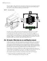
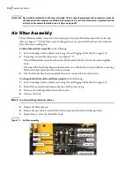
Air Filter Assembly
The air filter assembly is composed of two main parts: the water filter element and the coalescing
filter (see Figure 7
7). Both filters must be changed twice a year and both bowls must be drained at
the end of every working day.
To bleed the air filter assembly
, do the following:
1.
Lock out and tag out the vehicle (see
Locking Out and Tagging Out the Vehicle
2.
Using a rag, unscrew the drain screws (see Figure 7
7).
This will bleed all the water from the water filter bowl and all the air from the coalescing filter
bowl.
The water filter bowl helps keep residual moisture out of the body air system while the coalescing
filter bowl helps capture particles in the air stream.
3.
Once both bowls have been completely drained, screw back the two drain screws.
To change both filters of the air filter assembly
, do the following:
1.
Lock out and tag out the vehicle (see
Locking Out and Tagging Out the Vehicle
2.
Shut off the air supply and depressurize the unit before servicing.
3.
Unscrew the retaining collar of one of the bowls.
4.
Unscrew the bowl.
N
OTE
:
Avoid scratching internal surfaces.
5.
Replace the filter element.
6.
Reverse the procedure to reinstall the other components (bowl and retaining collar).
7.
Repeat Steps 3 - 6 for the other filter bowl.
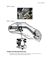
Figure 7
-
7 Air filter assembly
Bowl
Retaining collar
Drain screw
Bowl
Retaining collar
Drain screw
Coalescing filter
Water filter
Bypass indicator
Summary of Contents for EXPERT
Page 1: ...EXPERT TM MAINTENANCE MANUAL...
Page 2: ......
Page 3: ...EXPERT MAINTENANCE MANUAL...
Page 10: ...viii Table of Contents...
Page 18: ...8 Introduction...
Page 244: ...234 General Maintenance...
Page 251: ...Lubrication 241 Figure 4 11 Glass compartment lubrication chart optional...
Page 252: ...242 Lubrication Figure 4 12 EXPERT lubrication chart...
Page 264: ...254 Lubrication...
Page 320: ...310 Hydraulic System...
Page 357: ...Troubleshooting 349...
Page 358: ...350 Troubleshooting...
Page 386: ...378 Multiplexing...