


180
Lifting Arm
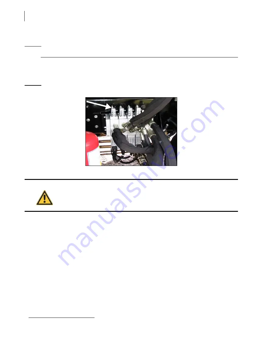
Adjusting Arm Speed
N
OTE
:
No arm speed adjustment is required unless replacing the valve or one of its sections.
Arm speed is controlled by the amount of hydraulic fluid (flow) that is being sent to the arm cylinder.
The arm control valve spools can limit the flow of hydraulic oil, depending on the section of the
valve
1
. Flow is limited by two movement restrictors located on each section.
Figure 10-19 Movement restrictor
To adjust arm speed:
1.
Lock out and tag out the vehicle (see
Locking out and Taging Out the Vehicle
2.
Secure the area around the path of the arm with barrier tape or barricades.
3.
Put the transmission in Neutral, start the engine, and engage the hydraulic pump.
4.
Clearly identify the stopper screw on the valve that corresponds to the proper function (boom
extension/retraction, gripper open/close).
5.
Move the lever to evaluate arm speed, then release the lever.
6.
Loosen the locknut.
7.
Turn the restrictor adjustment screw only one eighth (1/8th) of a turn at a time to see a
significant change of the arm speed.
8.
Move the lever again to evaluate arm speed. Repeat until cycle times are properly set (see
Operating Pressure and Cycle Times
9.
Tighten back the locknut.
1.
Limiting spool strokes limits the quantity of oil (flow) going through them. Controlling the flow of oil means controlling arm speed.
Danger!
Do not stand in the path of the arm while carrying out these adjustments.
Summary of Contents for Automizer Versa Hand
Page 1: ...AUTOMIZER VERSA HANDTM MAINTENANCE MANUAL...
Page 2: ......
Page 3: ...AUTOMIZER VERSA HAND MAINTENANCE MANUAL...
Page 26: ...18 Safety...
Page 89: ...Lubrication 81 Figure 4 11 Lubrication chart Automizer...
Page 90: ...82 Lubrication Figure 4 12 Lubrication chart Versa Hand arm...
Page 94: ...86 Lubrication Figure 4 18 Cylinder retaining ring Cylinder retaining ring...
Page 95: ...Lubrication 87 Packer Lubrication Points...
Page 96: ...88 Lubrication Hopper Door Hopper door latch Hopper door hinges...
Page 105: ...Hydraulic System 97...
Page 127: ...Hydraulic System 119 Figure 5 29 Detecting cylinder internal leaks 1 2 3 4 5 A A A...
Page 128: ...120 Hydraulic System Main Hydraulic Schematic...
Page 129: ...Hydraulic System 121 Hydraulic Schematic 96 Gallon Gripper...
Page 130: ...122 Hydraulic System Hydraulic Schematic 300 Gallon Gripper...
Page 131: ...Hydraulic System 123...
Page 132: ...124 Hydraulic System...
Page 137: ...Electrical System 129 Electrical Schematics Console 1...
Page 138: ...130 Electrical System Console 2...
Page 139: ...Electrical System 131 Arm Control...
Page 140: ...132 Electrical System Chassis...
Page 141: ...Electrical System 133 Main Body...
Page 142: ...134 Electrical System Hopper...
Page 143: ...Electrical System 135 Arm...
Page 144: ...136 Electrical System...
Page 151: ...Pneumatic System 143 Pneumatic System Schematic...
Page 152: ...144 Pneumatic System...
Page 155: ...Troubleshooting 147 Figure 8 4 Ball end hex wrench metric and SAE...
Page 164: ...156 Troubleshooting Figure 8 9 Tailgate locking mechanism...
Page 166: ...158 Troubleshooting...
Page 189: ...Lifting Arm 181...


