background image

12 | MSD Legend Series Operation & Maintenance Manual

InSit

e Contr

ol Bo

x

Ex

ca

vat

or Batt

er

y Main 

Dis

connect S

wit

ch

Po

w

er / E

xt

ension Cable

Run Do

wn E

xc

av

at

or Boom

INSITE

 PO

WER

 C

ABLE

 WIRING

 DIA

GRAM

Summary of Contents for MSD Series

Page 1: ...EAR SAFETY OPERATION MAINTENANCE 516649 User Manual 1 2020 Ver 5 MSD LaBounty 1538 Hwy 2 Two Harbors MN 55616 1 800 522 5059 www stanleyinfrastructure com brands labounty www stanleyinfrastructure com...

Page 2: ...contact any authorized LaBounty dealer You may also download a PDF copy at www stanleyinfrastructure com REGISTRATION FORM The Warranty Registration Form must be filled out by the dealer or customer...

Page 3: ...e You Start 15 Safety Devices 15 Technical Specifications 16 Controls 16 Operating Tips 17 Bleed the Shear Hydraulic Circuit 18 Bleed InSite 19 Check for Leaks 20 MAINTENANCE 21 8 Hour Inspection Chec...

Page 4: ...he basic rules are summarized in this section of the manual They also appear throughout the manual along with additional specific rules for safety and operation GENERAL If the attachment is not functi...

Page 5: ...perate tag to the machine BASE MACHINE Ensure that the cab is equipped with the proper safety guards for LaBounty applications The cab MUST be equipped with an approved Falling Object Protection Struc...

Page 6: ...bal Materials Attachment Model Serial Number Year of Manufacture Weight Model Serial Number Plate 511045 Figure 2 Patent Plate 116404 Figure 3 Top and front cab guarding required during any material p...

Page 7: ...IALNUMBER UPPERSHEAR PIERCING TIPS LOWER SHEAR MAIN PIVOT GROUP STICK SHEARBODY STICK BOOM CONNECTION LINKAGE CYLINDER CONNECTION UPPER CUTTING BLADES TRANSPORTPIN HYDRAULIC MANIFOLD BLOCK REAR CYLIND...

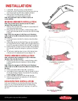
Page 8: ...ection 5 Extend the arm cylinder rod and connect the cylinder to the cylinder connection using the cylinder connection pin 6 If you have a rotating shear remove the transport pin and place it in its s...

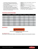
Page 9: ...PSI 275 380 Bar 8 10 GPM 30 42 LPM 2000 2500 PSI 138 172 Bar Cylinder 1 25 inch Code 62 Rotation 8 FFORX MSD 2500 140 GPM 530 LPM 4000 5500 PSI 275 380 Bar 8 11 GPM 30 45 LPM 2000 2500 PSI 138 172 Bar...

Page 10: ...d reduce downtime InSite requires DC power from the excavator Run Power Cable Up the Excavator Boom Ensure all electrical power is turned off and the main battery disconnect switch is in the open posi...

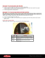
Page 11: ...ed to wire directly to the ignition switch You may make this connection to any terminal that is electrically connected to the ignition switch as long as InSite power will be OFF when the excavator key...

Page 12: ...12 MSD Legend Series Operation Maintenance Manual InSite Control Box Excavator Battery Main Disconnect Switch Power Extension Cable Run Down Excavator Boom INSITE POWER CABLE WIRING DIAGRAM...

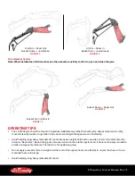
Page 13: ...ote The InSite application is required to finalize installation and access shear data REMOVING THE SHEAR FROM THE EXCAVATOR 1 Position the shear on the ground under the excavator boom as far as the st...

Page 14: ...contamination of the hydraulic oil 8 Ensure the shear is properly blocked up and can receive the total weight of the shear 9 Remove the boom pin from the shear STORING THE SHEAR 1 Grease the shear as...

Page 15: ...immediate proximity to the work being done Check the location of cables gas lines and water mains before operation Ensure work site footing has sufficient strength to support the machine When working...

Page 16: ...tor Weight 3rd Member Attachment Weight Jaw Opening Jaw Depth Reach MSD 2250 44 000 Lbs 20 mTons 88 000 Lbs 40 mTons 10 600 Lbs 4 800 Kg 30 In 760 mm 30 In 760 mm 8 6 Ft 2 6 M MSD2250R 53 000 Lbs 24 m...

Page 17: ...er than with jerky abrupt movements Jerky movements will provide a rough ride in the cab and could give the appearance of instability Avoid handling long heavy materials off center Excessive weight he...

Page 18: ...ack of maintenance can lead to greater problems and potential downtime Only use the force of the cylinder to cut material Do not attempt to apply other forces on the shear to aid in material processin...

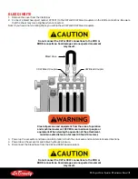
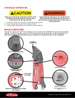
Page 19: ...ed movement may result Bleed Hose CCW Bleed Coupler CW Bleed Coupler Clear all persons and equipment from the area of operation and machine movement NEVER move loads over people or equipment When view...

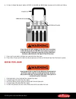
Page 20: ...lly open and close the shear jaws 8 Power down the excavator relieve hydraulic pressure and remove the bleed hose from the bleed couplers CHECK FOR LEAKS Keep hands and body away from pinholes and noz...

Page 21: ...ble bearing if equipped see Shear Lubrication on page 23 _________ Lubricate the planetary gearbox if equipped see Planetary Gearbox Lubrication on page 24 Inspect bolts and hydraulic fittings _______...

Page 22: ...ation ________ Second Rotation ________ Third Rotation ________ Fourth Rotation _________ Inspect the cylinder gap see Check the Cylinder Gap on page 42 Inspected By __________________________________...

Page 23: ...Check the hydraulic oil reservoir and ensure it is filled 3 Visually inspect all hydraulic hoses and lines for leaks or damage SHEAR LUBRICATION Use premium grease No 2EP Grease fittings are shown wit...

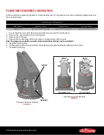
Page 24: ...4 F 1 Ensure the shear is on hard flat ground and has been secured for maintenance 2 Remove the cover plate from the rotating head 3 Remove the oil fill plug 4 Remove the oil drain plug Drain the oil...

Page 25: ...s 1220 Nm M30 10 9 1200 Ft Lbs 1630 Nm Hydraulic Flange Fastener Torque Table Size Class Cap screw Size Torque 0 75 61 M10 x 1 50 45 Ft Lbs 65 Nm 1 00 61 M10 x 1 50 45 Ft Lbs 65 Nm 1 25 61 M12 x 1 75...

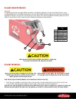
Page 26: ...at all times during blade maintenance Hands may be exposed to hazards cuts abrasions and heat BLADE REMOVAL Wear personal protection equipment at all times This includes eye protection hard hat steel...

Page 27: ...nd cause severe injury 2 If the blades are not loose tap on the blade face with a soft faced mallet 3 Use a pry bar between the blade and blade seat to loosen the blade Do not strike the blade bolts d...

Page 28: ...sh or a needle scaler if necessary 3 Use a grinder to clean up blade edges Remove sharp burrs and smooth out deformations Note Use caution when cleaning the blade seat Excessive grinding will damage t...

Page 29: ...upper and lower secondary blades overlap 2 Measure the gap in multiple places using a feeler gauge The gap should be less than 030 762 inches Note For most applications a gap of 010 020 inches 254 508...

Page 30: ...n the bolts that hold the lower primary blade in the blade seat 5 Slide the blade so you can access the adjustment plate 6 Add shims between the blade and adjustment plate until the gap is specified i...

Page 31: ...l four edges see Figure 28 Figure 29 The blades must be rotated every 80 hours when the blade edge is rounded to 25 radius or if the blade is damaged Some special applications will require a more freq...

Page 32: ...ROTATION In the second rotation remove each blade perform a 180 roll rotation then move it to a different blade seat The piercing tip blades will also be rotated If you are using the shear in a heavy...

Page 33: ...er secondary blade and set aside 7 Remove the upper primary blade Rotate the blade along the long edge 180 Roll Rotation 5 Rotate the previously set aside lower secondary blade step 1 along the long e...

Page 34: ...lower primary blade seat 11 The mating surfaces of the piercing tip must be clean to ensure a tight fit Inspect all mating surfaces on the piercing tip blades and blade seat Ensure there is no dirt or...

Page 35: ...he tip blades Ensure the clearance is within the specification found in the table below If there is no clearance clean the blade and seat as shown in step 11 15 Once installed shim all cutting blades...

Page 36: ...lade rotation will be performed exactly the same as the first rotation After completing the third rotation order a complete LaBounty blade kit as all blades will need to be discarded and replaced with...

Page 37: ...e the upper blades 4 With the shear still upside down remove both piercing tips Clean the mating surface of the blade seats as shown in 3rd Rotation on page 36 Replace with new tips Replace upper blad...

Page 38: ...ick Electrodes E7018 E8018 C3 Gas Metal Arc Welding Solid Wire Electrodes ER70S 6 Gas Metal Arc Welding Flux Cored Electrodes E71T 1 E71T 1M E80T1 Ni1 E80T1 Ni1M Gas Metal Arc Welding Metal Powder Cor...

Page 39: ...st be grounded when welding to prevent the possibility of electric shock Lower Jaw Build Up Locations Figure 32 BUILD UP TEMPLATE Hardsurfacing Recommendations Some attachments have hardsurfacing inst...

Page 40: ...ted slag peener Note Check the temperature often Maintain 300 400 F 149 205 C during build up Hardsurface 4 Apply a bead of Amalloy 814H rod directly on top of each underlayment bead Note Do not apply...

Page 41: ...e each pass by peening and grind the welds smooth 7 Wrap the area with a heat blanket and allow to cool slowly SLIDE SCREW ADJUSTMENT The slide screw keeps the upper jaw in line and cutting properly T...

Page 42: ...d the head face as shown in Figure 36 Cylinder Gap Measuring the Cylinder Gap Figure 36 If the cylinder gap exceeds the value in the Maximum Cylinder Gap table contact the LaBounty Service Department...

Page 43: ...y from pin holes and nozzles which can eject fluids under high pressure Use a piece of cardboard to search for leaks Escaping fluid under pressure can penetrate the skin and cause serious injury If AN...

Page 44: ...ll the poppet valve into the pilot valve and torque to 73 ft lbs 100 Nm Adjusting the Speed Valve Note Do not adjust the speed valve while the cylinder is moving 1 Fully close the shear jaws 2 Turn th...

Page 45: ...MSD Legend Series Operation Maintenance Manual 45 SPEED VALVE ASSEMBLY ILLUSTRATIONS Test Port Locations...

Page 46: ...1569 1 Valve Cap 4 511548 1 End Stop 7 511515 5 Screw Plug Torque to 15 ft lbs 20 Nm 8 513086 2 Screw Plug Torque to 15 ft lbs 20 Nm 9 513087 7 Screw Plug Torque to 7 ft lbs 10 Nm 10 513877 1 Check Va...

Page 47: ...M6 x 8 9 512322 1 Orifice D1 M5 x 6 10 511562 1 Valve Seat D10 1 x 23 11 512323 8 Cap Screw M5 Torque to 1 5 ft lbs 2 Nm 12 511514 10 Cap Screw M8 x 1 Torque to 7 5 ft lbs 10 Nm Pilot Valve Assembly I...

Page 48: ...intenance Manual Check Valve Assembly Check Valve Assembly Item Part Number Qty Description 1 513875 1 Check Valve Housing 2 511580 1 Plunger 4 511578 1 Spring 5 511579 1 Screw Plug Torque to 103 ft l...

Page 49: ...MSD Legend Series Operation Maintenance Manual 49 HYDRAULIC SCHEMATICS HYDRAULIC SCHEMATIC STANDARD ROTATING SHEARS HYDRAULIC SCHEMATIC STANDARD NON ROTATING SHEARS...

Page 50: ......

Page 51: ......

Page 52: ...your dealer or the LaBounty parts department and requesting a CE Operation Maintenance manual You must include the attachment model number and serial number LaBounty 1538 Hwy 2 Two Harbors MN 55616 1...

Reviews: