background image

Anorectal Manometry 

 Nexam Pro User Manual 

113 

9.2.2 

Select the Catheter  

Anorectal manometry investigations can be performed by either using (a) 
water catheters with DT-NN pressure transducers, (b) air-charged catheters 

with external pressure transducers or (c) solid state catheters. LABORIE 
advises to use catheters with 4 pressure channels for the most accurate 

results.  


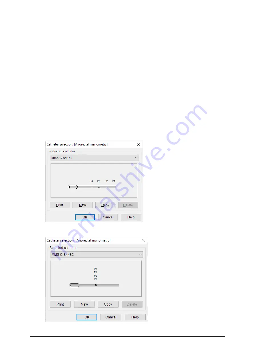
The layout of the two most common 4-channel catheters is displayed in 

Figures 9.2 and 9.3: 

  one cm spacing between the four pressure channels (spiral) and a balloon 

at the tip in order to test the anorectal reflex (RAIR) and sensations. 

  four pressure channels at the same location (radial) with an angle of 90 

degrees and a balloon at the tip in order to test the anorectal reflex (RAIR) 

and sensations. 


Figure 9.2

 Anorectal manometry catheter, spiral


Figure 9.3

 Anorectal manometry catheter, radial


Summary of Contents for Nexam Pro CIM

Page 1: ...Nexam Pro User Manual...

Page 2: ...3 4803701 www laborie com MMS is a registered trademark of Medical Measurement Systems BV Enschede the Netherlands All rights reserved IMAGES RENDERINGS OF LABORIE DEVICES IN THIS PUBLICATION ARE PROP...

Page 3: ...lect the Patient 24 2 4 Start the Measurement Program 25 2 5 Prepare the Investigation Pre Test 26 2 5 1 Start the Pre Test 26 2 5 2 Consumables Traceability 26 2 5 3 Pre Test 30 2 5 4 Install the Pum...

Page 4: ...ves and Pura 69 3 6 5 Flushing and Zeroing Water Catheters 71 4 Uroflowmetry 73 4 1 Introduction 73 4 2 Channels 73 4 3 Investigation 73 4 4 Results 74 5 Cystometry 77 5 1 Introduction 77 5 2 Channels...

Page 5: ...1 Balloon Expulsion 124 9 2 12 Profiles 125 9 3 Prepare the Investigation 126 9 3 1 Water Catheters 126 9 3 2 Air Charged Catheters 127 9 3 3 Solid State Catheters 129 9 3 4 Positioning of the Cathete...

Page 6: ...5 13 Balloon Expulsion Test 158 9 5 14 Rectal Compliance 159 9 5 15 3D Vector Volume Plot 160 9 5 16 Rectal Volume Plot 161 10 Biofeedback 163 10 1 Introduction 163 10 2 Prepare the Investigation 163...

Page 7: ...1 12 5 6 Sensation Markers 202 12 5 7 Investigation Specific Settings 203 12 5 8 Channel Settings 205 12 5 9 Connections Nexam Pro 206 12 6 System Settings 207 12 7 Filling Liquid Settings 209 13 Anal...

Page 8: ...Flow plot 230 13 5 10 WF Volume Plot 231 13 5 11 Blaivas Detrusor Flow Plot 232 13 5 12 Composite Nomogram 233 13 6 Settings 234 13 6 1 Menu Overview 234 13 6 2 Channel Settings 235 13 6 3 System Sett...

Page 9: ...trolley system For air charged catheters and solid state catheters LABORIE systems catalog code U8 3 and Nexam Pro CIM trolley system For water catheters and pressure transducers with Argon or Memscap...

Page 10: ...r to design a system to meet their requirements LABORIE offers custom made modules for measuring pressures EMG conductance and flow Software modules are available for different types of investigations...

Page 11: ...ages may be different because of Nexam Pro hardware and software changes Module Description U2M module Interface main module between computer and Nexam Pro modules STF Separating Transformer standard...

Page 12: ...e can measure four pressures and one EMG signal via a wireless or a wired connection Catheter puller The wireless puller withdraws the catheter with constant speed to obtain a pressure profile optiona...

Page 13: ...eports and archiving patient and testing information Designated catheters and accessories are required for measurement in each specific area General indications for use include patients with lower uri...

Page 14: ...re not able to solve the problem contact your LABORIE representative 1 6 LABORIE Software Program The LABORIE software program is provided on USB or DVD and should be installed on the computer to make...

Page 15: ...atabase program Analysis program Figure 1 3 LABORIE software program 1 7 Computer Requirements The minimum computer requirements for the LABORIE Windows software for the Nexam Pro system are as follow...

Page 16: ...er you can disable the appearance of the LABORIE assistant Figure 1 4 LABORIE assistant 1 9 About the Manuals The Nexam Pro User s Manual is intended for all users of the Nexam Pro measurement system...

Page 17: ...0075 MAN 032 HRAM option HRAM User s Manual LBL 001028 HRAM Service Installation Manual MAN 00037 Hardware and software changes After receiving new manuals always keep the old manuals as supplied with...

Page 18: ...tton appears in bold for example click the Print report button Figure 1 5 Screen Choose Report Print report means that you need to click Report on the menu bar and then choose Print report Press a but...

Page 19: ...he user to the possibility of a problem with the device associated with its use or misuse Such malfunctions include device malfunction device failure damage to the device or damage to other property N...

Page 20: ...ry and biofeedback Chapter 11 explains the Luna module and the procedure to switch from stationary to ambulatory measurement The investigation procedure can be as follows Start the LABORIE database pr...

Page 21: ...Figure 2 1 The Login window 2 2 1 Administrator Authentication From the Login window click the button to open the Administrator Authentication window to manage the User Password Figure 2 2 The Admini...

Page 22: ...twork software changes you can enter them in the following fields Local dir for the location of the locally installed software Network dir for the location of the files on the network Use Cache dir to...

Page 23: ...rt Set the LDAP Base DN Groups which is the base node from which all groups will be searched recursively Set the LDAP Base DN Users which is the base node from which all users will be searched In Perm...

Page 24: ...t with all patients and the investigations performed on the selected patient Select the patient by clicking their name All the studies performed on the selected patient are displayed in the investigat...

Page 25: ...ou to save the modified data By default the entries Last name and Date of birth are obligatory Choose Settings System settings and then click the Configure patient entry tab to select the entries Pati...

Page 26: ...gation Pre Test 2 5 1 Start the Pre Test After selecting the investigation name in the measurement program the pre test will start Figure 2 8 Pre test pressure flow study 2 5 2 Consumables Traceabilit...

Page 27: ...e upper right corner You can reopen it by clicking the RFID button on the toolbar Scanning Consumables The Nexam software keeps track of your inventory in a repository which is displayed in the Consum...

Page 28: ...ly used consumables will be preselected and display the suffix reuse Consumable Expiration When consumables are within a month of their expiration date you will be notified and encouraged to use them...

Page 29: ...lay After an investigation is performed the used consumables will be shown in the database next to the preview of the investigation Figure 2 10 The consumables used during an investigation Consumables...

Page 30: ...bsections provide more information about installing the pump tube connecting EMG electrodes preparing the flowmeter and preparing the catheter puller In Chapter 3 you will find information about prepa...

Page 31: ...Pump Unit with bag of saline Control panel The control panel of the pump unit has the following Two white LEDs for indicating the rotation direction One status LED One flush button For more informatio...

Page 32: ...n When the pump tube and the bag of saline are installed on the pump unit there is air in the pump tube You can remove this air by using the Flush button on the pump unit The function is available onl...

Page 33: ...ing Figure 2 12 Rotation direction LEDs on control panel Install the pump tube The pump tube is connected to the saline bag and positioned in the pump This pump tube is connected to the filling lumen...

Page 34: ...lume transducer Install the pump tube as follows Start the pre test of the investigation Turn the lever of the pump 1 and take out the tube clamp 3 Unpack the pump tube Put the spike of the pump tube...

Page 35: ...the pump and can be set clockwise or counterclockwise in the diagnostic program see the Nexam Pro Service Installation Manual document code MAN 00031 Place the tube clamp do not stretch the tube whil...

Page 36: ...set in the investigation protocol This is essential as the infused volume is calculated by determining the decrease in weight of the infusion liquid If a video mix option is fitted the system will aut...

Page 37: ...te catheters air charged catheters or Sensonor Memscap transducers with water catheters Argon formerly B D connectors for DT XX transducers with water catheters Holders for DT XX or Memscap formerly S...

Page 38: ...3 Ground reference 4 EMG 6 pole DIN connector 5 Holder for DT XX transducers 2 5 6 Prepare the Luna Wireless Module The Luna module is a wireless interface for measurement of pressures EMG and or con...

Page 39: ...gure 2 20 shows the connectors on the back of the Luna Figure 2 20 Luna connectors 1 Lemo 3 EMG channel 2 Lemo 3 conductance channel 3 Lemo 4 pressure channel Pves 4 Lemo 4 pressure channel Pabd 5 Lem...

Page 40: ...sh Indicates proper startup of WPM electronics during battery placement Green blinking Batteries are fully depleted temporary status Replace the batteries Blue blinking Indicates a wireless Bluetooth...

Page 41: ...y pressing on the cover forcing the small tab upward which can be used to remove the cover Insert the battery while noticing the polarity instructions as displayed in the battery compartment Figure 2...

Page 42: ...G electrode leads The WPU eS module contains RJ 45 receptacles for pressure e Sense catheters EMG receptacles for EMG electrode leads Figure 2 26 WPU L4 with its connectors 1 2 3 Lemo 4 connectors P1...

Page 43: ...PU can be affixed to the patient s leg by using an elastic disposable strap First place the strap on the patient s leg and shove the strap wings of the WPU onto the strap Figure 2 28 Leg strap It is i...

Page 44: ...des a description LED Indication for wireless application Indication for cable application Blue blinking Bluetooth communication Orange blinking Low battery WPU eS Catheter has passed its usage time W...

Page 45: ...s can be different depending on Type of the catheters solid state air charged or water catheters Pressure transducers used for water catheters DT XX or Memscap Number of pressures measured two or thre...

Page 46: ...electrodes are placed o Without releasing the buttocks dry the area free of any remaining moisture from the alcohol pad o Place the EMG electrode patches directly ON opposing sides of the sphincter T...

Page 47: ...odes with DIN 42802 and DIN 5 connector 180 cm MMS EMG PE disposable waterproof protected EMG surface electrodes including lead wires to be used with EMGC D5 TP guarded EMG cable for three electrodes...

Page 48: ...e EMG electrodes The color coding is as follows Signal Red Signal Black Reference Green Yellow The recommended EMG cable to use with the WPM or Luna is the UD 597 A6 guarded EMG cable for three surfac...

Page 49: ...etooth functionality Just connect a digital MMS bus cable between the flowsensor and one of the digital ports on the U2M module Second flowmeter It is always possible to connect a second flowmeter to...

Page 50: ...ected Reconnect the power adapter Bluetooth flowsensor in low power mode Bluetooth connection is lost In case you are using the Bluetooth USB dongle check if the USB dongle is missing or broken 2 5 12...

Page 51: ...n the puller proceed as follows Move the slider 7 to the catheter guide 11 until the catheter clamp 9 is positioned close to the catheter guide 11 Move the catheter through the catheter guide 11 to se...

Page 52: ...D Color Indication Bluetooth Blue blinking The Bluetooth catheter puller has a wireless connection with the computer Status Green on The puller is switched on and is functioning well Orange on IPL mod...

Page 53: ...ase note that the automatic return will become unavailable 2 6 Run Quality Check Click the Quality Check button to start the quality check The software will display a message instructing the patient t...

Page 54: ...not OK the failed channels are mentioned in the Result dialog box Figure 2 43 Results quality check failed The information of the last quality check will be stored in the investigation file and will...

Page 55: ...nstructions as described in the following chapters Uroflowmetry see Chapter 4 Cystometry see Chapter 5 Pressure flow study see Chapter 6 Urethra pressure profile UPP see Chapter 7 Gynecology study see...

Page 56: ...eport with a combination of different types of investigations of one patient It is also possible to print more than one report at once for example all reports of today You can find more information in...

Page 57: ...aximum temperature of 80 C 176 F Cleaning and disinfection of the slider guider plastic pinion and the cover of the motor house can be done with 70 alcohol Clean the outside of the puller and the carr...

Page 58: ...xit button to close the LABORIE analysis program Figure 2 46 Return to the database program Click the Exit button in the database program to close the LABORIE database program Shut down computer After...

Page 59: ...ending on the type of catheters and transducers used and the number of pressures measured You can find information about how to prepare reusable solid state catheters in 3 3 You can find information a...

Page 60: ...theter Prepare the EMG cables and apply the electrodes as described in 2 5 10 if applicable Prepare the catheter puller as described in 2 5 12 if applicable Click the Start investigation button to ini...

Page 61: ...ura at the maximum urethral pressure and fix the catheter Insert the rectal catheter into the rectum and fix the catheter Ask the patient to cough to check the registration of all pressures The spikes...

Page 62: ...essure and fix the catheter Insert the rectal catheter into the rectum and fix the catheter Ask the patient to cough to check the registration of all pressures The spikes of Pves Pabd and Pura should...

Page 63: ...e the catheters and transducers is as follows Connect the pressure transducer cables to the WPU module or Luna as follows Color pressure transducer WPU L4 or Luna Yellow P1 Pves vesical bladder pressu...

Page 64: ...sure transducer in OPEN position Press the Zero all button to zero all pressures to atmospheric pressure Charge the catheters Figure 3 9 Charge catheters Fix the abdominal catheter Withdraw the cathet...

Page 65: ...uct line The catheters are connected to the CIM or Luna via external pressure transducers In this section you will find instructions and illustrations explaining the setup of single use DT XX pressure...

Page 66: ...the pressure channels If there is no signal check if the stopcock is open to the catheter and not to atmosphere or if there is air in the transducer or catheter During the investigation you need to a...

Page 67: ...he pressure transducer P1 Pves Fix the catheter Insert the rectal catheter and connect the catheter to the pressure transducer P2 Pabd Fix the catheter Flush and zero the pressure transducers and cath...

Page 68: ...ducer at a flow rate of 60 ml per hour Disinfect the genital area Insert the bladder catheter and locate the vesical sensor Pves and the urethral sensor Pura both in the bladder Connect the catheter t...

Page 69: ...chapters 5 to 8 3 6 4 Measuring Pves and Pura For urethral pressure profiles UPP you can use the bladder catheter as displayed and described in 3 6 3 It is not necessary to measure the abdominal press...

Page 70: ...ital area Insert the bladder catheter and locate the vesical sensor Pves and the urethral sensor Pura both in the bladder Connect the catheter to the pressure transducer P1 Pves and the pressure trans...

Page 71: ...evel Connect the syringes filled with sterile water to the pressure transducers as displayed in Figure 3 17 optionally the LABORIE flush set can be used Push the blue flushing devices and flush the pr...

Page 72: ...ssures The spikes of Pves Pabd and Pura should rise equally in response to the cough and the detrusor pressure Pdet pressure should remain relatively flat If necessary you will need to flush and zero...

Page 73: ...2 5 11 Place the urine container on the flowsensor Position the patient on the micturition chair or commode Press the Start investigation button Press the Permission to void button to mark the miction...

Page 74: ...m the menu to display the calculated parameters Figure 4 1 shows the parameters that can be calculated Figure 4 1 Uroflow result selection Some parameters will be calculated after placing the correspo...

Page 75: ...arker is present and Flow markers are present the peak flow will be the flow at the second Flow marker Calculated Qmax F Time to Qmax The time to Qmax is the elapsed time from the onset of the flow to...

Page 76: ...time s When Flow markers are present the average flow rate is calculated between the first and last flow marker Corrected Qmax The corrected Qmax is the square root of the voiding volume Calculated Co...

Page 77: ...s P3 P1 calculated Conductance Cond Infused volume Vin EMG EMG Miction volume Vmic Miction flow Qura During a cystometry investigation the patient should be awake un anaesthetized and neither sedated...

Page 78: ...rate further filling or if the bladder is filled sufficiently press the Pump button to stop Press the Stop investigation button Enter the residual urine if prompted Remote control buttons Buttons Desc...

Page 79: ...ters can be calculated Figure 5 1 Cystometry result selection Some parameters will be calculated after placing the corresponding markers The parameters of the cystometry results are described below In...

Page 80: ...immediately following the completion of micturition It can be entered manually at the end of a cystometry Pves max Pves max is the maximum bladder pressure Pves during the investigation This paramete...

Page 81: ...5 2 Cystometry sensation results Pdet compliance Pdet compliance is the change in bladder volume for a change in detrusor pressure It is defined as C dV dP where dV is the volume increment and dP is t...

Page 82: ...va begin marker is present but when no leak point marker is placed the maximum pressure is shown in the table Cough results The cough results can be selected in the select results window During the CL...

Page 83: ...ts window When a leak point marker is present without valsalva marker or CLPP marker the leak point results table is displayed Leak point results Volume Pves Pabd Pdet 1 Leak point pressure 225 ml 150...

Page 84: ...egisters the miction flow and voided volume during micturition 6 2 Channels The following channels can be measured during a pressure flow study Vesical pressure Pves P1 Abdominal pressure Pabd P2 Uret...

Page 85: ...the Start investigation button Press the Pump ON button to start the pump Press the First sensation button to mark the first sensation Use this button for all sensation markers When the patient is una...

Page 86: ...et during the pre test and if necessary during the measurement Press Valsalva begin end to start end the Valsalva maneuver Click Spontaneous Miction to mark spontaneous miction Press Shift and Leakpoi...

Page 87: ...ameters of the pressure flow results for the filling phase and the voiding phase are described below 6 4 1 Filling Phase Results Sensation results For all sensation markers present in a Pressure flow...

Page 88: ...tion It can be entered manually at the end of a Pressure flow study Volume lost through leakage The volume lost through leakage is all urine lost during the filling phase of the pressure flow study me...

Page 89: ...d values are substituted by a hyphen when only the volume is measured VOID 340 BOOI and BCI When selected in the results the BOOI shows the Bladder Outlet Obstruction Index Pdet Qmax 2Qmax The ICS nom...

Page 90: ...ual to flow time Calculated Voiding time D Average flow The average flow is the total voided volume divided by the flow time The average flow rate is only meaningful if flow is continuous and without...

Page 91: ...otal infused volume This is explained if the volume produced by diuresis during the investigation is taken into account Computed residual urine Total bladder capacity Voided volume Init Bladder filing...

Page 92: ...Initial bladder filling Infused volume Extra infused volume Voided volume residual urine Total bladder capacity Flow delay time Normally there is a time lag in the flow registration of 0 5 1 second be...

Page 93: ...bladder emptying The BVE treatment of lower urinary tract symptoms LUTS suggestive can be defined as a percentage BVE voided volume total bladder capacity 100 The BVE can be seen in addition to the co...

Page 94: ...P study can be performed manually or by using a catheter puller The pull speed can be set in the investigation protocol see 12 5 7 7 2 Channels The following channels can be measured during a UPP inve...

Page 95: ...solid state catheters see 3 4 o Water catheters see 3 6 Do not fix the bladder catheter Locate the vesical sensor Pves and the urethral sensor Pura both in the bladder and watch the graphs carefully C...

Page 96: ...the profile Position both sensors Pves and Pura in the bladder Stress profile manual pull Press the Start Pull button to mark the start of the profile note this is an immediate marker The metronome wi...

Page 97: ...s profile use the catheter puller Press the Start Puller button to start the puller Ask the patient to cough every two seconds The peaks caused by coughing are used to calculate transmissions An incre...

Page 98: ...ressure Profile Dr Eberhard The extended UPP analysis is according to Dr J Eberhard This UPP analysis analyzes all profiles found in the investigation It differentiates between rest profiles and stres...

Page 99: ...2 UPP results selection The parameters of the UPP results are described below Maximal urethral pressure MUP The maximal urethral pressure Pura during the UPP study Functional profile length The funct...

Page 100: ...theter during the investigation Pulling the catheter manually yields unpredictable erroneous results due to variations and inaccuracy in pulling speed The puller speed as set in the protocol is used t...

Page 101: ...al Closure Pressure MUCP Calculation method The Maximum Urethral Closure Pressure MUCP can be calculated in two ways MUCP Max Pura Pves ura MUCP Max Pura Pves default In the analysis program you can d...

Page 102: ...cmH2O Pura 0 indicates the end of the urethra providing the transducers were zeroed at atmospheric pressure Calculated Profile length Pullerspeed T Pura 0 Tprofile A profile end marker can be placed b...

Page 103: ...ce and area related parameters Other parameters You can find more information about the calculation of other parameters by clicking the Help button in the Results window 7 4 3 Transmission Figure 7 5...

Page 104: ...nsmission along the urethra The transmission profile graph can only be displayed for stress profiles The software distinguishes between stress and rest profiles by the presence of transmission markers...

Page 105: ...Urethral pressure profiles are performed with a partially filled bladder You can repeat this procedure for different bladder fillings The UPP part of the study can be performed manually or by using a...

Page 106: ...catheter puller as described in 2 5 12 if applicable Move the puller clamp to the tip of the puller arm Position the puller in front of the urethra and mount the catheter on the puller clamp Do not f...

Page 107: ...e bladder and continue with the filling phase Stress profile manual pull Press the Start Pull button to mark the start of the profile note this is an immediate marker The metronome will help you to pu...

Page 108: ...rt the puller Ask the patient to cough every two seconds The peaks caused by coughing are used to calculate transmissions An increase in urethral pressure Pura indicates that the urethral sensor enter...

Page 109: ...tton to mark leakage Press the Voiding phase button to mark end filling phase The investigation is now temporarily halted Reposition the patient if necessary Voiding phase Press the Start voiding phas...

Page 110: ...Leak Point Pressure procedure CLPP Ask the patient to cough the software will insert cough markers around the peaks Press Leak point to mark a leak point Click Spontaneous Miction to mark spontaneous...

Page 111: ...al manometry investigation the following tests are available 4 Resting pressure Squeeze Endurance squeeze Cough Push Rectal anal inhibitory reflex RAIR Sensation test Anal rest profile Anal squeeze pr...

Page 112: ...page is shown with settings regarding the use of the printer sample rate marker line distance and so on Under normal circumstances the default settings are sufficient For anorectal manometry you must...

Page 113: ...channels for the most accurate results The layout of the two most common 4 channel catheters is displayed in Figures 9 2 and 9 3 one cm spacing between the four pressure channels spiral and a balloon...

Page 114: ...heter insertion depth during the investigation you can use the Go to x cm button puller or the Mark x cm button manual pull When right clicking this button the x cm is reset to initial value when a pu...

Page 115: ...ring the investigation use the U button to move the selected test in the Use column up Use the D button to move it down NOTE Most tests can be combined in one single investigation It is up to the inve...

Page 116: ...setting and the List selection is applicable for the syringe filling method for the Sensation test You can enter the volume increment e g 10 ml or edit a complete list e g 10 10 10 20 20 9 2 5 Timers...

Page 117: ...9 6 Timers tab The familiarization timer default on is used to let the patient get used to the catheter at the beginning of the investigation 9 2 6 Squeeze Click the More button and then select the Sq...

Page 118: ...can mark the catheter position insertion depth The settings are often used for investigations with radial catheters The puller can be used to withdraw the catheter step wise default 1 cm 9 2 7 Push Cl...

Page 119: ...olume default 10 ml and the volume increment default 10 ml under Volume on the Push tab On the Filling tab you can set the filling method For syringe filling method you can select Ask balloon volume o...

Page 120: ...rement that will be added to the previous inflation volume after the balloon has been inflated For example If the physician would like to assess the RAIR with the following inflation volumes 10 20 30...

Page 121: ...setting For syringe filling method you can select Ask balloon volume on the Filling tab After inserting the RAIR end marker during the test the software will ask to enter the balloon volume 9 2 9 Sens...

Page 122: ...ings On the Filling tab you can set the filling method For the syringe filling method you can enter the volume increment e g 10 ml or edit a complete list e g 10 10 10 20 20 on the Filling tab You can...

Page 123: ...loon compliance can be determined each time at the start of the test or determined once and saved if you always use the same type of balloon Use standard balloon calibration Because the balloon has a...

Page 124: ...atically with the MPP Plus is recommended 9 2 11 Balloon Expulsion Click the More button and then select the Balloon expulsion tab The window shown in Figure 9 13 is displayed Figure 9 13 Balloon expu...

Page 125: ...ile settings Rest and squeeze profile tests can be performed during anorectal manometry A 4 channel radial catheter is most accurate for these tests In the profile settings you can select how to withd...

Page 126: ...omatically places the profile end marker 9 3 Prepare the Investigation 9 3 1 Water Catheters For measuring with water catheters and pressure transducers perfusion of the channels is needed in case a p...

Page 127: ...sure cuff Open the clamp of the 4 way catheter flushing set to start perfusion Flush the pressure transducers and catheter Make sure that there are no air bubbles left Press the Zero all after 10 seco...

Page 128: ...n the database program Click the Anorectal manometry button to start the pre test Connect the catheter to the pressure transducers follow the colors Be sure to connect in the OPEN position Calibrate t...

Page 129: ...abase program Click the Anorectal manometry button to start the pre test Connect the pre wetted catheter to the CIM module Press the Zero all button to zero all pressures to atmospheric pressure Inser...

Page 130: ...sting pressure Squeeze Endurance squeeze Cough Push Rectal anal inhibitory reflex RAIR Sensation Rectal compliance Anal rest profile Anal squeeze profile Balloon expulsion test During an anorectal man...

Page 131: ...nt of voluntary sphincter capability at one or more levels in the sphincter Press the Next test button until the text Squeeze is displayed on the left button Ask the patient to squeeze Press the Squee...

Page 132: ...tomatically when the endurance squeeze timer is used see protocol settings Repeat this procedure if necessary 9 4 5 Cough Test The purpose of the cough test is to obtain an assessment of voluntary sph...

Page 133: ...Press the Next test button until the text RAIR is displayed on the left button Fill the syringe with air according to the volume displayed on the Syringe button in the upper left corner of the screen...

Page 134: ...the baseline pressure this is a delayed marker Wait about 40 seconds to settle all pressures before repeating this procedure The balloon volume is always absolute what means that the balloon is deflat...

Page 135: ...ording to the volume displayed on the Syringe button in the upper left corner of the screen e g 10 ml Connect the syringe to the three way stopcock which is attached to the central lumen of the cathet...

Page 136: ...n First urge Modest urge Intense urge Maximum tolerable volume and Pain When the maximum tolerable volume is reached stop inflating the balloon by clicking the Inflate balloon button again Press the S...

Page 137: ...or manually In this section you will find a description of the test using the puller When pressures are measured radially throughout the sphincter the software can create cross sectional and longitudi...

Page 138: ...e in anal pressure is at the marker line Press the Anal Squeeze profile button to mark the start of the test Wait until the drop of anal pressure to zero reaches the marker line Press the Profile end...

Page 139: ...in the rectum The procedure is as follows Press the Next test button until the text Start profile Rest is displayed on the left button Press the Start profile Rest button A window is displayed with t...

Page 140: ...ose of the balloon expulsion test is to determine if the patient can expel a balloon filled with a certain volume The filled balloon simulates the feces Therefore the best way to perform this test is...

Page 141: ...laced on the pump of the Nexam Pro The filling speed is displayed on the Pump button in the upper left corner of the screen e g 10 ml Press the Pump button to start the pump The balloon in the rectum...

Page 142: ...ial or Success and then click OK 9 4 12 Rectal Compliance The purpose of the compliance measurement is to objectively determine the compliance of the rectum The compliance can be used to determine abn...

Page 143: ...ompliance only once Measurement The balloon should now be inflated with 10 ml increments and the resulting pressure at each step is recorded If you want to increment in other steps than 10 ml press th...

Page 144: ...by the balloon If you always use the same balloon catheter you need to determine the balloon compliance only once Measurement Inflate the balloon with the perfusion pump click the pump tool button Th...

Page 145: ...other value on the cm or balloon button Zero all pressures during the measurement Press Alt first and then Zero all during the measurement to zero all pressures 9 4 14 Stop the Investigation To stop t...

Page 146: ...orm analysis for each test After you set this you can save the settings as default For the next investigation if performed with the same catheter and in the same way you can use these settings again W...

Page 147: ...l Anal Sphincter A drop in pressure after inflating the balloon indicates the internal sphincter In the window channel P3 is defined as IAS This implies that for the RAIR test only channel P3 is analy...

Page 148: ...d cough results are calculated either on channels that are defined as EAS in the channel definition Settings Channel definition or on certain user selectable channels To select the channels yourself c...

Page 149: ...o The 2 Marker RAIR mode is recommended 5 Marker RAIR is still supported for users who are used to it Compliance calculation settings When balloon compliance calibration is performed the compliance ca...

Page 150: ...d by clicking the Help button in the Results window 9 5 5 Resting Pressure Test For the resting pressures a table with the average pressure between the markers can be displayed The level at which the...

Page 151: ...re 9 26 Squeeze test The letters between square brackets refer to the corresponding letters in the above figure During the squeeze test the patient squeezes their External Anal Sphincter The beginning...

Page 152: ...or Diagram can be constructed The VVP will use the maximum pressure on each channel between the cm markers in order to create a squeeze VVP 9 5 7 Endurance Squeeze Test The squeezes should be marked w...

Page 153: ...l automatically insert two channel markers C and D The first channel marker will be placed on the maximum EAS pressure between marker A and B The second channel marker will be placed at a specified sq...

Page 154: ...an select which of these tables should be included in the results Resting pressure The resting pressure is the pressure at the cough begin marker Maximum pressure The maximum cough pressure is calcula...

Page 155: ...begin marker A Residual pressure The residual pressure is the minimum pressure between the two push markers B relaxation The relaxation is calculated as 100 Residual pressure Resting pressure Duration...

Page 156: ...n The of relaxation is defined as the Amplitude of relaxation divided by the resting pressure multiplied by 100 It is the percentage of IAS relaxation relative to zero pressure Amplitude of relaxation...

Page 157: ...sults will be calculated Sensation volume Pressure at sensation Sensation results are displayed for all sensation markers present in the investigation If multiple markers of the same sensation type ar...

Page 158: ...the average for each distance is also calculated and included in the table In the results a profile pressure table can be included This table displays the pressures for each channel over a certain dis...

Page 159: ...in printed reports Figure 9 31 Rectal compliance test The letters between square brackets refer to the corresponding letters in Figure 9 31 The compliance is the change in volume for a change in pres...

Page 160: ...ysis software click the 3D Vector volume plot button to display the 3D vector volume plot Three dimensional imaging of the anal sphincter can be used to evaluate sphincter dysfunction Figure 9 32 Dime...

Page 161: ...ght In the vector volume plot header the type and number of the profile on which the VVP is based are displayed Two buttons are added to the toolbar with which you can select the previous or next VVP...

Page 162: ...clude the rectal volume plot in the report select Rectal volume plot in the Report setup The X axis represents volume auto scale The Y axis represents rectal pressure auto scale When filling with air...

Page 163: ...e measured signal i e EMG pressure etc by a moving object For example a fish can be displayed in a sea world When the fish is catching air bubbles the patient is doing good Figure 10 1 Biofeedback on...

Page 164: ...heme challenge time or resting time for more information see 10 5 2 If you want to return to the main screen of the measurement program you need to click the Menu button Figure 10 2 Biofeedback settin...

Page 165: ...Ask the patient to cough to check the registration of the pressure Auto scale It is possible to set the scale automatically as follows Let the patient relax for a while Ask the patient to squeeze for...

Page 166: ...re calculates the minimum value over a moving time window of 400 msec Heartbeat filter disabled for the EMG channel Click to enabled Heartbeat filter enabled for the EMG channel Click to disable Show...

Page 167: ...ng the investigation you can autoscale toggle curves on off or toggle the heartbeat filter on and off Changes in the settings like challenge time and or resting time can still be done Editing the chal...

Page 168: ...Analysis In the analysis program the measurement is shown as conventional graphs The challenge markers show the start of a challenge Every time a challenge has changed during the investigation a new...

Page 169: ...made in the protocol settings and saved with the OK button are stored for the protocol With the More button changes in the Biofeedback settings can be made for more information see 10 5 2 However dur...

Page 170: ...ion protocol window 10 5 2 Biofeedback Settings The Biofeedback settings window can be opened in different ways If you want to save the changes as default protocol settings do the following In the Edi...

Page 171: ...review of the challenge is displayed Figure 10 9 Biofeedback settings for two channels A challenge consists mostly out of challenge time and resting time The challenge time is the worktime with a cert...

Page 172: ...e This is possible only if you enter the settings from the protocol and not during the pre test or investigation A window shows the possible themes To select another theme click the image of your choi...

Page 173: ...ditor All available challenges are shown on the left side The current selected challenge can be recognized on the orange border The default available challenges are shown at the top the background col...

Page 174: ...2 Edit challenge window Basic edit mode In the basic edit mode you can adapt the work level or the rest value of a challenge A challenge consists of one or more work levels A work level defines a goal...

Page 175: ...to the next work level In the advance edit mode you can add a new part remove parts in the challenge and change levels of each part Figure 10 13 Challenge structure Click the Advanced edit button to...

Page 176: ...an be moved To add a part right click on an anchor To return to the Basic edit window you need to click the Basic edit button In the basic edit mode you can save the challenge by clicking the Save but...

Page 177: ...The Luna is now recording data and the patient is free to go Stop recording when you want Protocol setting With the protocol settings Enable continuation with ambulatory Urodynamics on the General tab...

Page 178: ...e by clicking on it The LCD display shows standby Figure 11 1 Select Luna After a connection between the Luna and the computer had been established the LCD display shows stationary NOTE You cannot con...

Page 179: ...he measurement program to enter the database program The measurement is now available for analysis 11 3 From Stationary to Ambulatory Measurement With the ambulatory software option you can continue t...

Page 180: ...apter 11 Click Yes to continue Figure 11 4 Select protocol Select the protocol Click the Continue investigation button to proceed with the measurement To change the battery the following window appear...

Page 181: ...eless Module Nexam Pro User Manual 181 Disconnect the catheter and change the battery Figure 11 6 Reconnect catheter After changing the battery reconnect the catheter Check catheter position Figure 11...

Page 182: ...rmation and the procedure when the patient returns 11 4 Analysis Two measurements can be analyzed after finishing the investigation the stationary measurement and the ambulatory measurement with the s...

Page 183: ...y system Figure 12 1 Measurement program The measurement window displays nine investigation protocols that you can select You can find more information about the settings in investigation protocols in...

Page 184: ...See the Nexam Pro Service Installation Manual for the registration procedure About View the about box with information about the software Exit Exit the software program 12 3 Investigation Select the...

Page 185: ...stigation type and the type of catheters being used 12 3 2 Start Measurement In the pre test click the Start investigation button or press the corresponding key on the remote control to start the actu...

Page 186: ...During an investigation the status bar is displayed at the bottom of the screen The status bar displays the following information Memory Computer memory available to store an investigation Infused Th...

Page 187: ...ero the detrusor pressure Pdet during the pre test and if necessary during the measurement During the pre test with the urethral sensor in the bladder you can use this button to equalize the urethral...

Page 188: ...he investigation the LED has different functions See the table below Note that the RC 1600 must first be registered in the measurement program before you can work with it see the Nexam Pro Service Ins...

Page 189: ...eck if the Bluetooth Smart USB long range dongle is missing or broken Batteries The remote control operates with three AAA batteries preferably alkaline It is recommended to replace batteries every si...

Page 190: ...button varies throughout the program The function is indicated by the software Next sensation anorectal sensation test 2 Square The function of this button varies throughout the program The function i...

Page 191: ...Marker A B C D Place user definable marker A B C D immediate during investigation Place user definable marker A B C D delayed during investigation F1 F4 F buttons No function yet No function yet 5 Pu...

Page 192: ...evious test anorectal Remove sensation marker cystometry gynecology pressure flow Decrease EMG audio volume 16 Next Select next test anorectal Skip squeeze command biofeedback Show next sensation in m...

Page 193: ...e ALTernate functions anorectal 24 Asterics No function yet No function yet When you press the Shift key on the keyboard during pre test or investigation some extra buttons become available that are n...

Page 194: ...ctivated 12 3 6 Markers During an investigation markers can be placed to indicate interesting events or to invoke calculation of parameters Markers are displayed as colored vertical lines on the scree...

Page 195: ...stand can be indicated by setting a position marker Position markers can be placed by clicking the buttons on the screen Audio comment marker immediate marker When a sound card is present you can add...

Page 196: ...in the investigation protocol the field Confirm stop investigation is set to Yes the investigation is not immediately stopped You may continue or confirm stop investigation After performing an investi...

Page 197: ...Figure 12 7 Select protocol When the measurement program is started the window shows default one investigation protocol More protocols can be added see below The investigation protocol contains diffe...

Page 198: ...d then choose Copy protocol or if you are in the protocol use the Copy all button Figure 12 8 Copy protocol Via the drop down menu choose the destination for the copied protocol In the Protocol name f...

Page 199: ...lude them if they were excluded This can be done by selecting the checkbox adjacent to the investigation type When an investigation is excluded the corresponding tab with investigation specific settin...

Page 200: ...e information about the use of immediate or delayed markers in 12 3 6 Show sticky note Will show the user definable markers as a sticky note on the screen during a measurement Quick options Quick star...

Page 201: ...t you can enable a warning at the start of the investigation to indicate when the vesical pressure Pves the abdominal pressure Pabd and the detrusor pressure Pdet are not within a certain range You ca...

Page 202: ...ring cystometry pressure flow and gynecology studies Figure 12 13 sensation markers Select the checkboxes of the sensations markers that you want to use for the cystometry pressure flow and gynecology...

Page 203: ...with settings regarding settings for printing the report storage on disk initial pump speed sample rate marker line distance and so on Some settings are Print report Save report to PDF Stop time urofl...

Page 204: ...ration will be saved per protocol per investigation type The printer and PDF settings will be saved globally for all protocols but only for the reports which will be created after the measurement You...

Page 205: ...ws an overview of all available channels For each investigation you can set the following The channels to be measured for example Pves Pabd Pura EMG The channels to be calculated for example Pdet Pclo...

Page 206: ...nels button see 12 5 8 For each channel signal to be measured you must select the channel number In this example Pves is measured on channel 1 of the CIM module Pabd is measured on channel 2 Pura is m...

Page 207: ...marker names marker names will be displayed vertically instead of horizontally which prevents marker names from overlapping If you select filled chained markers chained markers such as begin and end m...

Page 208: ...gh speed EMG is possible for specific hardware modules Neuro module CIM or WPU To use high speed EMG on the WPU the WPU must be connected using a digital cable to the system Bluetooth connection is no...

Page 209: ...input signal For more information see the Video User s Manual Reports You can set some report settings thick graphs tracing clip out time or video image 12 7 Filling Liquid Settings Choose Filling liq...

Page 210: ...n the middle of the screen is a vertical line called the cursor line This line can be moved through the graphs by moving the mouse In the left column you will see the channel name e g Pves EMG the cha...

Page 211: ...ts of the graph drag the scrollbar left or right or use the Page Up Down keys on your keyboard Auto scroll Scrolling is possible with a horizontal scrollbar and with the scroll wheel of the mouse Auto...

Page 212: ...It contains also results of the quality control Investigation memo Open a memo editor The physician who performed the investigation can write down important facts about the procedure This memo can be...

Page 213: ...opened via the Manuals menu in the database program 13 2 2 Display Results Choose Results Display results from the menu or click the Results button to display the dialog box shown in Figure 13 2 You...

Page 214: ...stigation memo to add comment to the investigation Click Save to PDF to save the results as PDF file Click Print to print the selected results only Click Help to show an explanation of the investigati...

Page 215: ...te investigation on the screen For more information see 13 3 2 Zoom out Restore the previous displayed screen For more information see 13 3 2 Zoom in Zoom in on the area around the cursor For more inf...

Page 216: ...zoom out and F6 zoom in Other fixed zoom intervals Zoom 4 minutes 15 minutes 1 hour and 4 hours 13 4 Marker 13 4 1 Menu Overview The following menu items are available Menu item Function Insert marker...

Page 217: ...cursor to the place where the marker should be inserted and then click to place the marker When the marker is part of a chained marker the next marker in the chain can now be placed by repeating this...

Page 218: ...the markers see the LABORIE help information in the analysis program Marker name Description Artefact This marker excludes data from the calculations For example coughing by the patient can cause an u...

Page 219: ...ht click the marker square and choose Comment to add comment to the marker Flow Determine which part of the voiding phase is used for the detrusor flow nomograms Further flow markers influence the way...

Page 220: ...ked with a delta symbol to indicate that they are calculated relative to the values at the reference cursor When the reference cursor is active you will see a check mark in front of this menu option Y...

Page 221: ...ology study see 13 5 7 Sch fer Detrusor flow plot Display the Sch fer detrusor flow plot in a pressure flow or gynecology study see 13 5 8 CHESS Detrusor flow plot Display the CHESS detrusor flow plot...

Page 222: ...the Manuals menu in the database program If you want to include the Blaivas plot for women only you need to enter the free Qmax first In the analysis program choose Options Detrusor flow plots accord...

Page 223: ...e vesical pressure at the start of the investigation 13 5 2 Siroky Flow Rate Nomogram The Siroky flow rate nomogram shows an x y plot of the flow rate related to the bladder volume It can be used as a...

Page 224: ...or choose Options Liverpool plot from the menu to display the plot Figure 13 8 Liverpool flow rate nomogram The Liverpool flow rate nomogram is age and gender dependent The results can be divided int...

Page 225: ...nu to display the plot Figure 13 9 Miskolc flow rate nomogram The Miskolc flow rate nomogram is used for children and is age and gender dependent The results of the Miskolc flow rate nomogram can be d...

Page 226: ...r Volume plot button or choose Options Detrusor Volume plot from the menu to display the plot Figure 13 10 Detrusor volume plot 13 5 6 ICS Detrusor Flow Plot The ICS detrusor flow plot shows an x y pl...

Page 227: ...tructed area the result is obvious However when the dot is in the equivocal area the outcome is not clear Read also P Abrams and C S Lim The Abrams Griffiths nomogram World journal of Urology volume 1...

Page 228: ...out 27 cm H2O correspond roughly to obstruction Read also D Griffiths et al 1989 Quantification of urethral resistance and bladder function during voiding with special reference to the effects of pros...

Page 229: ...peak flow and the detrusor pressure at peak flow determines the classes for the micturition Additional information about PURR The real pressure flow relations often shows complex patterns but is easy...

Page 230: ...No 3 August 1990 W Sch fer Analysis of bladder outlet function with the linearized passive urethral resistance relation World of Urology Volume 13 number 1 1995 Miguel Virseda Chamorro et al 1988 Car...

Page 231: ...ying with low pressure rise normal A4 low Pmuo high pressure increase needed to empty the bladder obstruction D1 high Pmuo low pressure increase needed to empty the bladder elastic BPH D4 high Pmuo hi...

Page 232: ...also Griffiths et al Quantification of Urethral Resistance and bladder function during voiding Neurology and Urodynamics 8 17 27 1989 13 5 11 Blaivas Detrusor Flow Plot Click the Det flow plot Blaivas...

Page 233: ...divided into four areas indicating no obstruction or mild moderate or severe obstruction Read also Jerry G Blaivas and Asnat Groutz Bladder Outlet Obstruction Nomogram for Women With Lower Urinary Tra...

Page 234: ...ams Bladder outlet obstruction index bladder contractility index and bladder voiding efficiency three simple indices to define bladder voiding function 13 6 Settings 13 6 1 Menu Overview Menu item Fun...

Page 235: ...e menu to display the dialog box shown in 13 18 Figure 13 18 Channel settings The channel settings window shows an overview of all available channels For the selected investigation you can change the...

Page 236: ...how to display a grid and to show the markers as full names If you select Vertical marker names marker names will be displayed vertically instead of horizontally which prevents marker names from overl...

Page 237: ...ral settings The option enter comment at event markers is selected by default If the option High speed EMG is available on the measurement system you can set the time base the default 20 ms Reports Yo...

Page 238: ...diately The report is printed or exported according to the report configuration and the printer PDF JPG settings of the LABORIE reporter program Print PDF JPG Graph Print or export the graph immediate...

Page 239: ...e button at the spot where you want to place the button To move a button on the bar do the following Click the button on the toolbar Press and hold down the mouse button and then move the button Relea...

Page 240: ...em must be purchased under the supervision of a physician For USA only Caution Federal law restricts this device to sale by or on the order of a physician The Nexam Pro measurement system complies wit...

Page 241: ...malfunctions include device malfunction device failure damage to the device or damage to other property NOTE The note sign appears when it is important to read the information Operating conditions Con...

Page 242: ...y for any part that has been opened adjusted or replaced by hospital personnel The Nexam Pro measurement system may be opened for any adjustment replacement maintenance or repair by LABORIE qualified...

Page 243: ...nt that is supplied as part of this system intended to be plugged into the Separating transformer module into a wall outlet The Separating transformer is a safety component designed to ensure Touch En...

Page 244: ...ect dedicated power supply for the U2M module is used before plugging it into a mains socket PS U2M T for trolley systems PS U2M P for non trolley systems WARNING Do not use a power supply other than...

Page 245: ...stem WARNING During a pre test the pump unit will not stop on over pressure CAUTION The pump tube needs to be replaced for each patient Long term usage of the tube will decrease the yield of the tube...

Page 246: ...UTION Change the battery only when the patient is disconnected from the Luna system unplug catheter and all patient leads from the Luna CAUTION Do not carry or use a mobile telephone during the measur...

Page 247: ...15 of the FCC Rules Operation is subject to the following two conditions 1 this device may not cause harmful interference and 2 this device must accept any interference received including interferenc...

Page 248: ...Do not bend the power cable forcibly or place a heavy object on the cable because it might damage the cable and cause fire or electric shock If the power cable is damaged discontinue use and replace...

Page 249: ...ot cause harmful interference and 2 this device must accept any interference received including interference that may cause undesired operation This device contains FCC ID POOWML C40XX WARNING Make su...

Page 250: ...e thick walls doors iron in walls doors may compromise the Bluetooth connection of the puller and battery lifetime Bluetooth Smart Long Range USB dongle BT SLR The BT SLR uses a transceiver module wh...

Page 251: ...cleaning the Nexam Pro measurement system to prevent damaging the electronics CAUTION Never allow water to get inside the Nexam Pro modules or any other part to prevent damage to the system Investiga...

Page 252: ...active You may lose data CAUTION Automatic safeguards built into the software should be seen as an aid They are not a substitute for careful personal monitoring and an alert investigator CAUTION Make...

Page 253: ...n as is specified in the manual electro magnetic fields caused by portable equipment as telephones computers X ray equipment radio transmitters radar equipment and so on Electrostatic Discharge mains...

Page 254: ...g Transformer STF Class I IP20 U2M module U2M Class II IPX1 Nexam Pump Unit NPU IPX2 Combination Interface Module CIM BF IPX1 Luna wireless module BF IP2X Wireless Patient Module WPM BF Wireless Patie...

Page 255: ...5 Blue symbol Refer to instruction manual Caution consult instructions of use Consult instructions for use Caution Federal law restricts this device to sale by or on the order of a physician Yellow t...

Page 256: ...eign objects of 12 5 mm and greater and not protected against liquids IP2X The enclosure provides protection of solid foreign objects with a diameter of 12 5 mm or more IP32 Protected against solid fo...

Page 257: ...s Symbol with red border Never put fingers or any other body parts in the pump while it is running Double insulated conform IEC 60601 1 Atmospheric pressure range 700 hPa to 1060 hPa Operating Conditi...

Page 258: ...90 non condensing Transport Conditions Temperature range 25 C to 70 C Transport Conditions Relative humidity range 90 non condensing This device uses a RF transceiver for data transfer purposes This...

Page 259: ...Explanation of Symbols Nexam Pro User Manual 259 Manufacturer May be combined with manufacturing date Keep dry Fuse Equipotentiality Protective earth Earth ground Signal reference...

Page 260: ...al Appendix B Polarity of DC power connection USB port upstream from U2M module to PC Input Output Input output Separating Transformer input and output voltage selection switch Mass including safe wor...

Page 261: ...mber SN YYXXNNNN SN Serial Number YY Two digit manufacturing year number XX One or two digit product identification number NNNN Four digit incrementing unique number Explanation of PE number PEYY FXXX...

Page 262: ...t found Communication problems Contact your LABORIE representative Bluetooth Stack s not initialized File s incompatible Communication problems Contact your LABORIE representative Bluetooth Stack s no...

Page 263: ...odule not connected Module expected but not connected Contact your LABORIE representative Digital EMG module not connected Highspeed EMG Module expected but not connected Contact your LABORIE represen...

Page 264: ...our LABORIE representative Flowmeter not connected Module expected but not connected Contact your LABORIE representative Flowmeter not connected The LABORIE bus devices can only be used when the follo...

Page 265: ...ntact your LABORIE representative No esophageal channels defined No Esophageal channel defined Define esophageal channels No Input signal present No video input signal available Contact your LABORIE r...

Page 266: ...cable Solar Blue is not connected Contact your LABORIE representative The Solar Blue system has lost the connection Communication problems Contact your LABORIE representative The Solar Blue system ha...

Page 267: ...ies Module expected but not connected Contact your LABORIE representative WPU not connected Check the Range of the Wireless patient unit Check the Bluetooth dongle or replace the batteries Module expe...

Page 268: ...of patient aborted FCU file is corrupted Contact your LABORIE representative Error in FCU file Restore of patient aborted FCU file is corrupted Contact your LABORIE representative Error loading queste...

Page 269: ...f investigations for the selected patient reached Select another patient name License file not correct install failed Incorrect license file Reinstall the software or contact your LABORIE representati...

Page 270: ...tions to resolve LABORIE representative This function is not available Network software but LABORIE login is not available Contact your LABORIE representative Unknown user Username Program halted Unkn...

Page 271: ...ctal manometry analysis settings 148 balloon expulsion test 140 cough test 132 edurance squeeze test 131 introduction 111 profiles using manual pull 138 profiles using puller 137 protocol settings 112...

Page 272: ...ransducers 65 71 Sensonor Memscap pressure transducers 65 solid state catheters 60 water catheters 65 Channel settings 205 235 CHESS detrusor flow plot 230 Cleaning instructions 56 Combination Interfa...

Page 273: ...7 to other file formats 237 F Flow markers 219 Flowmeter cleaning instructions 57 prepare 48 status LED 44 49 188 Flow reducer set for water catheters 68 Flush button Pump module 32 G Good Urodynamic...

Page 274: ...8 LED Flowmeter 44 49 188 LED s Puller wireless 52 Liverpool plot 224 Luna module 38 Luna Module back side 39 conductance connector 39 EMG connector 39 pressure connector 39 USB connector 39 Luna wire...

Page 275: ...P 101 Measurement program buttons in the software 185 186 channel information 185 edit protocol see Protocol settings 197 introduction 183 keyboard keys 193 marker line 185 MMS assistant 201 remote co...

Page 276: ...settings add protocol 197 anorectal manometry 112 channel settings 205 compliance 201 connections Nexam 206 copy protocol 197 delete protocol 197 edit protocol 197 general protocol settings 199 Good...

Page 277: ...fer detrusor flow plot 228 Sensation markers 202 Sensonor Memscap pressure transducers 65 Siroky plot 223 software program 14 Solid state catheters 60 Status LED Flowmeter 44 49 188 System settings an...

Page 278: ...results 82 Value marker 220 Voided volume 75 90 Voiding time 75 90 W Water catheters 65 DT XX pressure transducers 65 flushing water catheters 71 Sensonor Memscap pressure transducers 65 zeroing wate...

Reviews: