


Chapter 6: Maintaining the Nano Enclosure
Product Service 1-800-522-7658
34
5.
Once the alarm condition is set, use a small screwdriver to turn the
adjustment screw on the airflow switch counterclockwise (facing the
screw) until the “low” airflow red LED lights and the audible flow alarm
sounds.
6.
Adjust the inflow velocity to the nominal operating point required by your
Safety Officer.
7.
Over time the ULPA filter will load and eventually slow the inflow
velocity. Once the alarm condition is met, simply increase the speed
control outlined in Chapter 6 or replace the ULPA filter if the speed control
is maximized.
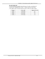
8.
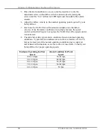
The table below lists typical alarm conditions based on normal operating
conditions. Typical alarm conditions are set at face velocities of 10 to 30
feet per minute below the normal operating conditions due to supply air
and exhaust air fluctuations, as well as room air cross drafts. Consult your
Safety Officer for proper operating speeds.
Enclosure Operating In-Flow
Speed
Alarm Condition Set Point
Speed
100 ± 10 fpm
70-90 fpm
90 ± 10 fpm
60-80 fpm
80 ± 10 fpm
50-70 fpm
70 ± 10 fpm
50-60 fpm
60 ± 10 fpm
50 fpm