
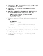


195
Example 2
– Blower Relay Contact (Three Phase AC)
The Blower set of contacts (Relay 1, pins 2 & 3) will indicate when the cabinet
’s blower is on.
On an A2 cabinet, this contact will close once the blower key is
pressed on the cabinet’s
keypad, and remain closed while the blower is at Normal Speed.
However, on a B2 cabinet, the contacts will close when the blower key is pressed to signal
(throu
gh this Relay 1 contact) a remote exhaust blower to start. The cabinet’s blower will NOT
start until the internal Airflow Sensor verifies proper exhaust airflow from the remote exhaust
blower. Once the blower successfully starts, the contact will remain closed.
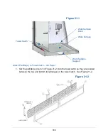
The generalized circuit shown below indicates how to interface the
cabinet’s provided contacts
to power a Three Phase high current device (like a remote exhaust blower).
Note that the
cabinet’s provided contacts are used to actuate the low-power coil of a user-supplied
external power relay/contactor. Never run high current or AC voltage through the
cabinet’s provided contacts!
The relay in the example below is: Potter & Brumfield P25P42D22P1-12, the 12V coil draws
.35Amps (the pr12VDC is fused at 0.5 Amps total, so choose a relay with an amp draw
for the actuator coil less than 0.5 A).
If using all three provided relay contacts, the sum total
of all current draw from three relay actuator coils must be less than 0.5A.
USER-
SUPPLIED
WIRES
2
3
8
1
Summary of Contents for Logic+ A2
Page 149: ...149 208 240V...
Page 151: ...151 Blower only will not start...
Page 152: ...152 Lights only will not illuminate...
Page 153: ...153 UV Light will not illuminate...
Page 154: ...154 Airflow Alert activating...
Page 155: ...155 Filter Life Gauge not at 100 when new...
Page 156: ...156 Contamination in the work area...
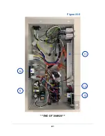
Page 200: ...200 Figure 23 4 1 2 4 3 5 7 6 8 8...
Page 201: ...201 END OF 3849920 Figure 23 5 9 10 11 12 13...


