LAARS Heating Systems
Page 16
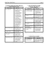
4. PRESSURE RELIEF VALVES LEAKING
INTERMITTENTLY OR STEADILY.
3. BOILER WILL NOT FIRE.
Possible Cause
What To Do
A. Electric power is off.
A. Check to see that main power
switch is “ON.” Use testing
device to trace power to
boiler junction box.
B. Operating or safety control has
B. Turn off power. Use continuity
opened circuit to electric
across terminals of each
gas valve.
operating and safety control
switch up to the electric gas
valve. Replace defective
control.
C. Pilot flame is out.
C. Relight pilot per instruction.
D. Manual reset device has tripped. D. Follow instructions for start-up.
Reset Pilot safety and all
manual reset safety switches
and reset manual safety gas
valve.
E. No gas pressure to burners.
E. Trace gas line to service shutoff
cock. If service cock is open,
trace gas line to meter. If no
pressure is present at meter,
call for public utility service. If
gas is present in boiler inlet,
check pressures in following
sequence: (1) downstream from
pressure regulator;
(2) downstream from electric gas
valve. Replace or adjust as
necessary.
F. Electric gas valve operator is
F. Disconnect wiring harness at gas
burned out or shortened.
valve terminals. Check continuity
to actuator coil. If open circuit or
short is indicated, replace coil or
operator.
Possible Cause
What To Do
A. Static pressure in system
A. Calculate height of water in
exceeds setting of relief valve.
system above boiler. Install new
valve with psi setting 25% above
required static system working
pressure. Do not exceed 160 psi.
B. Expansion tank is waterlogged
B. Drain expansion tank, then
(if installed).
reopen it to the system. Look for
leaks in expansion tank or
fittings. Calculate required
volume of expansion tank in
relation to system to determine
that tank is adequate.
SECTION 5.
Troubleshooting and Analysis of
Service Problems
1.
For proper service and problem diagnosis of the
heater and heater system, the following tools are
required:
a.
Gas pressure test kit with range from zero
to 14 W.C. Either a slack tub manometer or
an accurate gas pressure gauge is
acceptable with proper adapters which will
connect to the available fittings in the line
and on the gas valve.
b.
Multi-meter with the following ranges:
0 to 500 volts A.C.
0 to 1000 ohms continuity.
c.
Tube cleaning kit consisting of reamer,
stainless steel brush, speed handle and
handle extensions.
d.
Strap on digital temperature gauge to check
temperature rise.
2.
In addition, the boiler should be equipped with a
system pressure gauge with proper ranges for
boiler operation.


