background image

Page 48

4.17  Electrical Wiring Connections

  This appliance must be electrically grounded. Ensure the electrical receptacle that the combination boiler will 

be plugged into, is properly grounded; if wiring directly.

  Do not attach the ground wire to either the gas or the water piping as plastic pipe or dielectric unions may 

isolate the Combination boiler electrically.

  The wiring diagrams contained in this manual are for reference purposes only.

  Refer to these diagrams and diagrams from external controls used with this appliance. Read, understand, 

and follow all wiring instructions. 

  Do not disconnect the power supply when the unit is in normal operation. Damage caused by freezing is 

not covered under the warranty.

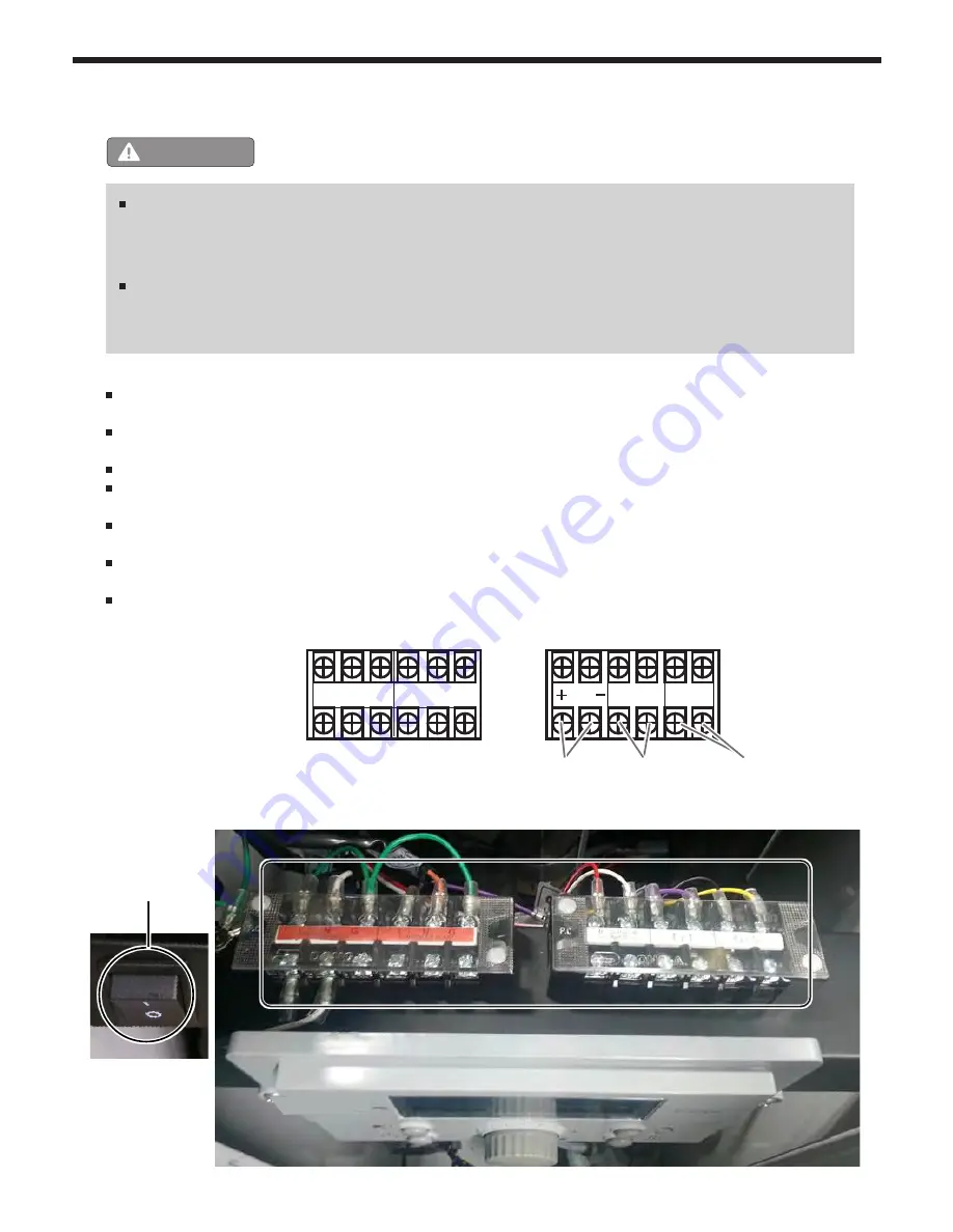
  Manual(Rocker) switch maximum allowable current for each circulator is 16 amps at 125VAC. 

   ( Housing : Nylon #66 UL 94V-2 , Rocker : Nylon #66 UL 94V-2, Terminal : Copper Alloy )

  Terminal  block  (External  power  connector)  : 

DFT-20A-10P (20 amps at 300VAC)

WARNING

  Install wiring and electrically ground boiler in accordance with authority having jurisdiction or, in the 

absence of such requirements, follow the National Electrical Code, NFPA 70, and/or CSA C22.1 

Electrical Code-Part 1 in Canada.

  ELECTRICAL  SHOCK  HAZARD  —  For  your  safety,  turn  off  electrical  power  supply  at  service 

entrance panel before making any electrical connections to avoid possible electric shock hazard. 

Failure to do so can cause severe personal injury or death.

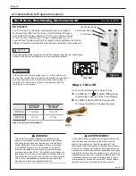
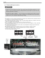
Manual 

Power 

Switch

Thermostat 
Connection

External 

Input 

Main Power

CH/Boiler 

Pump

Outdoor 
 Sensor

0 - 10V

L   N   G

L   N   G

T T

O / S

0-10V 

INPUT

R       W

Terminal Block

Summary of Contents for FTCF140

Page 1: ...uld cause serious injury property damage or death Improper installation and or operation will void the warranty AVERTISSEMENT Assurez vous de bien suivres les instructions donn es dans cette notice po...

Page 2: ...ines 42 4 14 1 External Plumbing and Water Conn Guidelines 42 4 14 2 Applicable Backflow Preventer 42 4 14 3 Closed type Expansion tank 42 4 14 4 Diaphragm Type Expansion Tank 42 4 14 5 Zoning with Ci...

Page 3: ...t the manufacturer and request a replacement conversion kit NOTICE If your installation altitude is greater than 2000 ft please check that the High Altitude Installer Setting has been adjusted to suit...

Page 4: ...the Unit continued Items Descriptions Qty Mesh screen 3 mesh 2 Outdoor Sensor with Screws and Anchors 1 Pressure Relief Valve CH LINE 3 4 30psi 1 Auto Fill Valve and Backflow Preventer Valves are NOT...

Page 5: ...9 9 FUEL N Natural P Propane CONFIG F Floor Stnd ALTITUDE A 0 10 000 Feet REVISION 1 First OPTIONS X Standard PUMP N with Pump 1 M SECTION 2 Product Characteristics 2 1 Model Nomenclature model number...

Page 6: ...t Off Device Gas Valve Operation Detector Exhaust Temperature High Limit Switch Water Temperature High Limit Switch 800 900 9276 Fax 800 559 1583 Customer Service Service Advisors 20 Industrial Way Ro...

Page 7: ...5 WC combustion readings At this point just record the CO2 readings at MAX Fire Do NOT attempt to adju CO2 at MAX Fire ONLY in MIN Fire so 18 Per Table B for MIN Fire change dip switch 6 to OFF and 7...

Page 8: ...DHW inlet Connection 3 4 NPT F Condensate 1 2 NPT G Drain 1 2 NPT 52 4 133 cm 15 7 40 cm 3 3 8 cm 9 2 23 cm 68 cm 9 3 2 7 4 3 4 3 5 8 9 2 3 7 12 9 18 7 23 27 3 30 39 3 3 0 7 6 cm 20 5 23 3 26 7 19 7 A...

Page 9: ...137 cm 15 7 40 cm 4 0 10 4 cm 6 6 16 9 cm 68 cm 18 9 2 6 4 3 4 3 5 7 8 8 3 7 12 5 18 2 22 5 26 8 29 4 48 3 17 9 23 3 26 7 19 7 3 0 7 6 cm 5 0 13 cm A B C D E F G TOP SIDE FRONT 3 O EXHAUST VENT GAS C...

Page 10: ...HW 13 DHW Tank Assembly 14 Water Drain Valve 15 Water Drain Adapter 16 Condensate Trap Adapter NO Name of Component 17 Condensate Drain Hose 18 DHW Inlet Adapter 19 Condensate Trap 20 DHW Outlet Adapt...

Page 11: ...16 Condensate Trap Adapter NO Name of Component 17 Condensate Drain Hose 18 DHW Inlet Adapter 19 Condensate Trap 20 DHW Outlet Adapter 21 Condensate Heat Exchanger Hose 22 CH Return Connection 23 CH S...

Page 12: ...ace Heating Water Supply Space Heating Water Supply Space Heating Water Supply Space Heating Water Supply Gas Inlet Space Heating Water Return Space Heating Water Return Space Heating Water Return Not...

Page 13: ...rating Mode Characteristics f Hot water mode Domestic Hot Water DHW mode Sub heat exchanger then cold water transformed into hot water DHW is controlled by the consumer It can provide hot water on dem...

Page 14: ...s exactly a fire or explosion could result causing property damage personal injury or loss of life A This appliance does not have a pilot It is equipped with an ignition device which automatically lig...

Page 15: ...O NOT use this Boiler if any part has been under water Immediately call a qualified technician for inspecting the Boiler and replacing any part of the control system and gas control which have been un...

Page 16: ...opened 5 Check the area around the appliance and remove any combustible or flammable materials Remove laundry or any other items that are on or near the boiler or vent pipe When in Operation CAUTION...

Page 17: ...th Electric shock may occur or internal parts may fail due to the exposure to moisture Do not disassemble the Boiler If repair is required call your local qualified technician After repair of gas pipe...

Page 18: ...ance Minimum Clearances For installation Suggested From Non Combustibles Service combustibles Clearance Top of appliance 15 in 38 cm 15 in 38 cm Back of appliance 5 8 in 1 6 cm 5 8 in 1 6 cm Front of...

Page 19: ...r during operation and service If new Combination boiler replaces an existing appliance check and correct system problems for example Do not install if System leaks causing oxygen corrosion or heat ex...

Page 20: ...g of all equipment in the enclosure When communicating to the outdoors through horizontal ducts each opening shall have a minimum free area of not less than 1square inch per 2000 Btu hr 1100 square mm...

Page 21: ...ation Code CAN CSA B149 1 or applicable provisions of the local building codes CAUTION NOTICE The instructions for the installation of the venting system shall specify that the horizontal portions of...

Page 22: ...w this manual and applicable codes may lead to property damage severe injury or death ___________________________________________ WARNING Use of cellular core PVC ASTM F891 cellular core CPVC or Radel...

Page 23: ...ly an electric damper draft hood or vent damper with this Boiler Do not locate vent termination where exposed to prevailing winds Moisture and ice may fall on surface around vent termination To preven...

Page 24: ...30cm 80 285 36 91cm inlet to building or the combustion air inlet 399 850 Other than Direct vent 4 ft 1 2m below 36 inches 91 cm to any other appliance or to side of opening 1 ft 30cm above opening NT...

Page 25: ...that the side wall horizontally vented gas fueled equipment is installed in a crawl space or an attic the hard wired carbon monoxide with alarm and battery back up may be installed on the next adjace...

Page 26: ...tre prises pour chaque appareil toujours raccord au syst me d vacuation commun et qui fonctionne alors que d autres appareils toujours raccord s au syst me d vacuation ne fonctionnent pas 1 Sceller to...

Page 27: ...the size of vent pipe 2 3 according to the installation conditions Push the pipe into the collar socket until it touches the bottom of the socket fitting For 2 installations install using the supplied...

Page 28: ...oor make up air is provided a minimum free area of 1 in2 per 1 000 BTU H 140 in2 13 1 4 W x 13 1 4 H 199 in2 13 1 4 W x 13 1 4 H 4 8 Vent Air Pipe Termination Shown is the FTCF140 The inlet and outlet...

Page 29: ...Exhaust Screen Exhaust Exhaust 12 MIN 1 MIN Sill Combustion Intake Combustion Intake SIDE VIEW FRONT VIEW Exterior Wall NOTE Must be 12 Minimum distance above highest anticipated snow level or grade...

Page 30: ...to 4 100mm Combustion Air Vent 12 30cm Minimum clearance above highest anticipate snow level Vent 12 Minimum clearance above highest anticipated snow level or grade whichever is greater 12 Minimum cl...

Page 31: ...appliance is fitted for the proper type of gas by checking the rating plate FT will function properly at elevations up to 10 000 feet 3050 m Refer to Section 4 12 for High Altitude Settings 2 For min...

Page 32: ...to the unit To facilitate any future maintenance it is also recommended that an approved gas union fitting be installed in the supply line between the shut off valve and the 3 4 male NPT connection on...

Page 33: ...4 FTCF199 Suggested Propane Gas LP Layout Suggested Natural Gas NG Layout Sediment Trap Other appliance Gas meter G Capacity Not less than total capacity of connected appliances AUTODESK AUTODESK AUTO...

Page 34: ...ve sea level If your Mascot FT is installed at an altitude of 2 000 ft or greater the correct altitude setting should be set according to Section 4 12 of the Mascot FT Install and Operating Manual bef...

Page 35: ...ted on ____ ____ ___to _____gas with kit ____________by______________________ name and company __________________________ accountable _________________________________ ________________________________...

Page 36: ...fire Refer to Table D for acceptable MIN fire combustion readings 12 If CO2 readings in Max Fire and MIN fire are acceptable then skip ahead to Step 13 If not then open the Gas Valve Adjustment Port b...

Page 37: ...Turn the dial E until 28 HA appears 3 Press the dial E 4 Set the high altitude value by turning the dial Refer to table The FT is shipped with a default factory setting for installation at an altitud...

Page 38: ...ervice Advisors 20 Industrial Way Rochester NH 03867 603 335 6300 Fax 603 335 3355 Applications Engineering 1869 Sismet Road Mississauga Ontario Canada L4W 1W8 905 238 0100 Fax 905 366 0130 www Laars...

Page 39: ...the Brass Fittings 10 Per Table B set DIP Switch 5 to the OFF setting the 5 DIP switch setting for LP Propane is the OFF side 11 Turn ON the GAS and WATER supply to the FT 12 Turn ON the FT 13 Connect...

Page 40: ...Refer to Table D for acceptable MAX fire combustion readings At this point just record the CO2 readings at MAX Fire Do NOT attempt to adjust CO2 at MAX Fire ONLY in MIN Fire so 18 Per Table B for MIN...

Page 41: ..._______________ H2373900C Manifold Pressure Port Gas Valve Adjustment Port under the cap screw Figure E 22 It may be necessary to go back and forth between HI Fire and LOW Fire several times and makin...

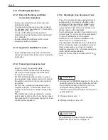
Page 42: ...wards tank 1 inch per 5 feet of piping DO NOT install automatic air vents on closed type expansion tank systems Air must remain in the system and return to the tank to provide its air cushion DO NOT u...

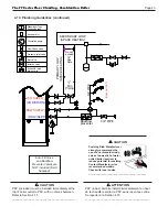
Page 43: ...TURN DHW SUPPLY Circulation pump Flow Check valve Expansion tank Air separator Diaphragm Type Pressure relief valve Ball valve Isolation valve PRIMARY LOOP SPACE HEATING 1 Min Piping Do not exceed 12...

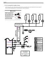
Page 44: ...iaphragm Type Pressure relief valve Ball valve Isolation valve PRIMARY LOOP SPACE HEATING 1 Min Piping Do not exceed 12 See Note Anti scald rated Mixing Valve ZONE 1 ZONE 2 ZONE 3 SECONDARY LOOP SPACE...

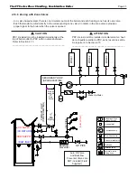
Page 45: ...ly at the top of boiler outlet to PRV with no valves between Refer to Section 4 15 __________________________________________ ATTENTION PRV inclus doit tre install imm diatement en haut de la chaudi r...

Page 46: ...CASE ACME F 82 This safety relief valve 30 psi is shipped loose for field installation An approved ASME HV Pressure Relief Valve must be installed on the DHW supply line as close to the unit as possi...

Page 47: ...heck the neutralizer every few months for depletion Apply only corrosion resistant materials for the condensate drain lines such as 1 2 PVC CPVC Polypropylene pipe or included plastic hose NOTICE Cate...

Page 48: ...ered under the warranty Manual Rocker switch maximum allowable current for each circulator is 16 amps at 125VAC Housing Nylon 66 UL 94V 2 Rocker Nylon 66 UL 94V 2 Terminal Copper Alloy Terminal block...

Page 49: ...r Max Fire change dip switch 6 to ON and 7 to OFF The unit will cycle up to MAX fire 17 WAIT for your combustion Analyzer to stabilize This may take up to 3 minutes depending on your combustion Analyz...

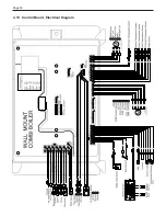
Page 50: ...Page 50 4 19 Control Board Electrical Diagram...

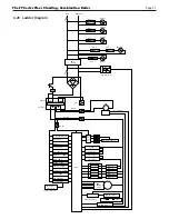
Page 51: ...t Primary Secondary Relay 3 Relay 4 Ignitor Relay 5 Gas Valve DC 14 V DC 30V DC 5V F B FAN Power Detector Burner Limit Speed Control Fan RPM Sensor DHM Driving circuit Over Heat TEMP 2 A Pump1 Relay 1...

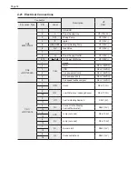
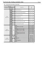
Page 52: ...ower COM Line HT 120V CN4 LWD1140 06D 1 FAN Unuse 2 GND SELV 26VDC 3 VDD SELV 14VDC 4 Fan power start coil SELV 26VDC 5 Fan power end coil SELV 26VDC 6 Fan speed feedback signal SELV 14VDC CN11 LWD114...

Page 53: ...r temperature sensor SELV 5VDC 13 7 SP S Over heat temperature sensor SELV 5VDC 14 CN14 SMW250 09D 1 IWM GND SELV 14VDC 2 DHM Stepper motor position SELV 14VDC 3 VDD SELV 14VDC 4 DHM Stepper motor coi...

Page 54: ...Status Display Mode If Display Power was Off Installer Mode C Hot Water DHW Set Point LOW Range 95 120 F 35 49 C DHW Set Point HIGH Range 121 140 F 49 5 60 C D Central Heat CH set point mode boiler o...

Page 55: ...ode Combination boiler Set Point can be adjusted Outside temp or 0 10 V mode Operating by outside temperature or 0 10V Numeric Display Domestic Hot Water Mode Anti Freeze Mode Storage Heating Lock Com...

Page 56: ...p checklist and briefly show a sequence of diagnostic codes before entering into the Operating Mode It will then display the following information Indicate Example Current Operating Temperature 110 F...

Page 57: ...rheat temperature L rt 1 PH Burner Operation Time Supply power time Supply power time x 100 hour 2 rh Burner operation time Burner operation time x 1 hour 3 rH Burner operation time Burner operation t...

Page 58: ...clockwise to decrease until desired temperature is reached Press dial E to save setpoint changes and to Exit Indicate Example Current DHW set point temperature 125 F Temperature sign Celsius or Fahren...

Page 59: ...ges and to Exit Default CH set point is 120 F 49 C CH set point range is 86 180 F 30 0 82 0 C Indicate Example Current Operating Temperature 110 F Temperature sign Celsius or Fahrenheit letter C or F...

Page 60: ...ating the water held in the internal storage tank When Storage Mode is active the display will appear as shown Turn the E dial clockwise to increase and counterclockwise to decrease setting Press E di...

Page 61: ...turning OFF the Power to the Display Control Then with the power to the Display Control OFF Press and HOLD more than 5 seconds the Button B to get into the Installer Mode Rotate Dial E until you find...

Page 62: ...0 F Default 180F 12 7 C less than Minimum Temperature to 82 C Default 82 C 17 cL Setting for Heating Minimum Temperature Range 86 F to 9 degrees F less than Maximum Temperature Default 86 F 30 C to 12...

Page 63: ...When the signal rises above 1 5 volts the appliance will ignite As the signal continues to rise towards its maximum of 10 volts the appliance will increase in set point temperature Adjust 16 cH and 17...

Page 64: ...e Flashing Indicate Example Error Er will flash Er 11 Error Code Er 11 Display and Controller are communicating NOTE When communication between the Control Display and the main controller is lost the...

Page 65: ...liance 3 Check Operating Temperature sensor at CH heat exchanger outlet If resistance is zero replace the sensor 4 If the problem persists replace the main control Hard Lock 20 Condensate Closed is No...

Page 66: ...sts replace the main control Hard Lock 41 Fan Speed too High with Flame On Press the Power button to clear the Error Code If Error happens again 1 Check the vent connections for blockages 2 Check the...

Page 67: ...the display and or the main control Soft Lock 80 Low Water Level Sensor Low Water Level Detected Four 4 Consecutive times This Error Code will go away when the condition is remedied If Error happens a...

Page 68: ...Page 68 6 2 Fault Tree Analysis 6 2 1 Flame detection...

Page 69: ...Fault Tree Analysis continued 6 2 2 Gas Detection 6 2 3 Storage DHW OP CH overheat Exhaust heat Sensor detects Error code contents E30 DHW Storage Temperature Sensor open or short E32 DHW NTC open or...

Page 70: ...that the gas supply type is correct Hot water temperature fluctuates at the opened tap Make sure that the filter in the cold water supply line is clean Make sure that the gas supply type is correct Ch...

Page 71: ...h to power boiler Is there 120 Volts at the service switch Troubleshoot and correct the power supply to the manual switch Is the ON OFF POWER SWITCH inside boiler case turned on Turn ON the manual pow...

Page 72: ...0 RPM when turned off Reset using manual reset screen on control panel Power button Check wire harness for loose connections and pin engagement at blower Connections Boiler in standby mode and blower...

Page 73: ...service technician if you notice any problems Check the relief valve Inspect the Combination boiler relief valve and the relief valve discharge pipe for any signs of weeping or leakage If the relief v...

Page 74: ...ny possibility of scalding from hot water If water flows freely release the lever and allow the valve to seat Watch the end of the relief valve discharge pipe to ensure that the valve does not weep af...

Page 75: ...ect the residual water inside the combination boiler 2 Press Power button on the front control panel to turn OFF the electrical power to the combination boiler 3 Turn off the gas valve 4 Close water s...

Page 76: ...ffects of reduced heat transfer and an increase in head pressure against the system circulator For example A 30 mixture of glycol will result in a BTU output loss of 15 with a 5 increase in head again...

Page 77: ...s Is the Boiler properly mounted on the wall Is there space for a drain which is close to the Boiler Are there any combustible materials near the Boiler and vent pipe Is the air supply sufficient for...

Page 78: ...elief valve of CH Plumbing at least 1 in diameter Is the pressure relief valve of DHW Plumbing at least 3 4 in diameter Have you installed the pressure relief valve on the hot water outlet pipe near t...

Page 79: ...The FT Series Floor Standing Combination Boiler Page 79 This page intentionally left blank...

Page 80: ...ng FT1604 16 3 Exhaust vent duct FT1611 16 4 Exhaust testing cap FT1606 Casing _ Feature Casing _ Feature List No Description Part Number Notes O 7 O Ring P7 FT1601 15 Air inlet duct Ass y FT1010 15 1...

Page 81: ...1019 24 Power switch FT1020 25 DHW Tank Cover BK FT1622 26 Casing Bottom FT1952 27 Front Cover Upper FT1911 28 Casing Bolt FT1830 29 Control display cover window FT1024 30 Condensate blockage Air pres...

Page 82: ...king FT1645 P 6 1 Packing FT1691 12 Flow sensor clip FT1208 58 Elbow Pipe connector 1 FT1648 Heat Exchanger FTCF140 Heat Exchanger Pump_ Feature List No Description Part Number Notes O 14 O Ring P14 F...

Page 83: ...paper FT1659 68 5 Burner FT1314 68 6 Burner case sealing O Ring FT1661 68 7 Ignition rod FT1315 68 8 Ignition rod gasket FT1316 68 9 Burner downside case FT1664 68 10 Refractory FT1665 69 Low level s...

Page 84: ...FT1703 55 18 O Ring adapter FT1704 56 Flow sensor FT1115 DHW Tank _ List No Description Part Number Notes O 14 O Ring P14 FT1642 O 15 O Ring P15 FT1685 O 16 O Ring P16 FT1643 O 18 O Ring P18 FT1687 P...

Page 85: ...91 Fan Ass y FT1714 91 1 Fan FT1715 91 2 Fan sealing O Ring ST1038 91 3 Gas mixer housing FT1409 91 4 Intake orifice FT1718 92 Mesh FT1720 93 Fan rubber packing 1 0t FT1721 94 Nozzle Ass y LNG FT1412...

Page 86: ...No Description Part Number Notes O 7 O Ring P7 FT1601 12 Exhaust vent duct Assembly FT1002 12 1 Stainless band 100 FT1603 12 2 Packing FT1604 12 3 Exhaust vent duct FT1611 12 4 Exhaust testing cap FT...

Page 87: ...fix bracket FT1828 22 Display Control P 920C FT1019 23 Bracket FT1910 24 Condensate blockage Air pressure switch FT1022 25 Front Cover Upper FT1911 26 Casing Bolt FT1830 27 Control display cover windo...

Page 88: ...16 O Ring P16 FT1643 O 22 O Ring P22 FT1644 P 6 1 Packing FT1691 10 Flow Sensor Clip FT1208 FTCF199 Heat Exchanger Heat Exchanger Pump_ Feature List No Description Part Number Notes O 16 O Ring P16 F...

Page 89: ...y FT1826 64 Flame detector sensor bracket FT1669 65 Flame detector sensor FT1327 66 Flame detector sensor cover FT1069 67 Low level sensor FT1325 68 Temperature sensor FT1324 69 Pipe for internal circ...

Page 90: ...Mixing valve FT1116 53 DHW Inlet pipe FT1835 54 Flow sensor FT1115 DHW Tank _ List No Description Part Number Not O 15 O Ring P15 FT1685 O 16 O Ring P16 FT1643 O 18 O Ring P18 FT1687 P 4 1 2 Packing F...

Page 91: ...1917 88 4 AGM O ring FT1774 88 5 AGM body FT1775 89 Stainless band 100 FT1603 90 Air intake hose FT1846 91 Stainless band 89 FT1777 92 Nylon Barb Y Fitting FT1918 93 Gas valve Assembly FT1847 93 1 Gas...

Page 92: ...ications subject to change without notice in accordance with our policy of continuous product improvement H2373000D 20 01 Document 1320D Customer Service and Product Support 800 900 9276 Fax 800 559 1...

Reviews: