L-3 Communications, Narda Safety Test Solutions
Page 8
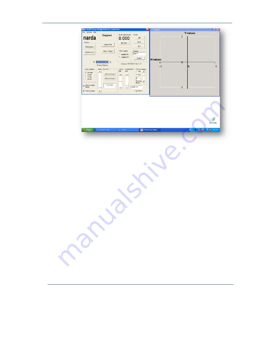
Narda 8950/10 Stray Voltage Detector
Begin displaying field levels by pressing the
Bandpass
button.
Your screen
should now look like this –
IPR2014-00839
Exhibit 2178
Page 8 of 15
Page 1: ...2010 Narda 8950 10 Stray Voltage Detection System Operation and Installation Guide Rev 1 IPR2014 00839 Exhibit 2178 Page 1 of 15 ...
Page 2: ...3 Welcome 3 System Description 3 Unpacking the System 4 Assembling the System 4 Chapter 2 System Operation 6 Software Controls and Their Functions 10 Logged Data 13 Troubleshooting 14 Replacement Parts List 14 Narda Warranty 15 T Ta ab bl le e o of f C Co on nt te en nt ts s IPR2014 00839 Exhibit 2178 Page 2 of 15 ...
Page 3: ...ruck and tested at speeds up to 20 mph and proven to be effective at detecting AC voltages as low as 2 VAC on objects that were 30 feet away Narda supplies a laptop computer that gives a user a visual and audible indication that a set threshold has been exceeded NOTE THIS DEVICE IS INTENDED ONLY FOR USE BY A PASSENGER IN A MOVING VEHICLE IT IS NOT RECOMMENDED TO BE USED IN MOVING VEHICLES WITH LES...
Page 4: ...upport assembly and slide the assembly in to the two inch receptacle Install the hardware only finger tight at this time The hitch support can be mounted in either an up or down configuration but in most mid and full sized trucks it can be used facing upwards Step 2 Installation of upper bed mounts Carefully swing arms out and around the end of the truck and position these above the truck s tie do...
Page 5: ...icle Sensor is placed between foam on the top bottom and sides of enclosure Note polarity of cable connection to sensor Depress ON OFF button and verify that light shows green LED This means sensor is ready for measurements Step 5 Connecting computer The fiber optic cable that was connected on one end to the upper bed mount needs to be connected to the laptop computer in the cab of the vehicle Alt...
Page 6: ...n Software Start up Software is started on the laptop computer by double clicking the L3 Icon on the desktop C Ch ha ap pt te er r 2 2 S Sy ys st te em m O Op pe er ra at ti io on n Initialize and understand software Logged Data format Verify system operation Troubleshooting IPR2014 00839 Exhibit 2178 Page 6 of 15 ...
Page 7: ...Below is the initial software display The left screen displays the controls for your system and the right side displays the graphical results The left screen default view is always in a basic display Move your mouse cursor up to the second menu item Settings and select Advanced from the menu Now your computer should be displaying the following IPR2014 00839 Exhibit 2178 Page 7 of 15 ...
Page 8: ...ions Narda Safety Test Solutions Page 8 Narda 8950 10 Stray Voltage Detector Begin displaying field levels by pressing the Bandpass button Your screen should now look like this IPR2014 00839 Exhibit 2178 Page 8 of 15 ...
Page 9: ...ge 9 Narda 8950 10 Stray Voltage Detector Active readings should be taking place and updating the plot on the right side If not re check the polarity of the cables insuring they are tight and connected correctly IPR2014 00839 Exhibit 2178 Page 9 of 15 ...
Page 10: ...Test Solutions Page 10 Narda 8950 10 Stray Voltage Detector Software Controls and Their Functions Let s take a closer look at each control and its function on the Stray Voltage Sensor Software IPR2014 00839 Exhibit 2178 Page 10 of 15 ...
Page 11: ...de fault Clears plot on screen does not clear data from log file Amount of charge left in probe Full blue bars means system is fully charged and will operate for up to 10 hours Numerical display of detected field levels Display scale on plot Unit can be set to auto range or to fixed scales such as 1 2 or 5 Volts full scale Default setting is auto range recommended setting for fixed range is normal...
Page 12: ...ic to sense fields emitted from any and all directions Users may find it useful to select an axis after the vehicle is stopped in order to better understand the direction left right front back or top bottom of the field Latches alarm indication once the set threshold has been exceeded Sets alarm threshold Users may choose from preset 2 0 and 4 0 V m levels or set any level between 1 0 and 10 V m S...
Page 13: ...te or location for easy recall of the computer If a new name is not assigned each day for instance the standard file is appended with corresponding date time and levels Logged Data When data is logged it is logged as a Comma Separated Value csv and can be displayed in Microsoft Excel as the following picture The first column denotes that time and date and also the markers if added Column B gives t...
Page 14: ...nsor battery is depleted 1 Open sensor housing and depress button for one second 2 Verify cables and RS 232 adapter are connected correctly 3 Charge Sensor Readings are displayed numerically but are not being plotted on screen Range is set too low Set to auto range or to a higher range Readings are unusually noisy Sensor is loose or improperly positioned Plot averaging is not enabled Open sensor h...
Page 15: ...STS product that has been disassembled modified physically or electrically damaged or any product that has been subjected to conditions exceeding the applicable specifications or ratings Narda STS shall not be liable for any direct or consequential injury loss or damage incurred through the use or the inability to use any Narda STS product Narda STS reserves the right to make design changes to any...