
Mechanical safety
Mechanical safety
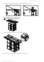
Flown congurations
The KARADOWNK2 rigging system complies with 2006/42/EC: Machinery Directive. It has been designed following
the guidelines of BGV-C1.
2006/42/EC: Machinery Directive species a safety factor of 4 against the rupture. The own deployments described in
this manual achieve a safety factor of
4
.
Refer to Soundvision for the safety factor of a specic deployment.
The
maximum limit
gives the maximum number of elements for which the safety factor can be compliant with the
2006/42/EC: Machinery Directive, when the other deployment parameters provide the best mechanical conditions.
For mixed arrays refer to your Soundvision model.
Always refer to Soundvision for the safety factor of a mixed array.
When ying a K2 array with a Kara downll, the mechanical safety of all system elements must be considered.
The indicated maximum limit applies to the KARADOWNK2 only.
Do not implement a pullback on a K2 array with a Kara downll.
K2 and Kara
conguration
rigging accessory
maximum limit
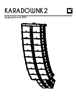
Vertical array with downll
KARADOWNK2
6 Kara
Assessing mechanical safety
Mechanical safety of the rigging system
Before any installation, always model the system in Soundvision and check the
Mechanical Data
section for
any
stress warning
or
stability warning
.
In order to assess the actual safety of any array conguration before implementation, refer to the following warnings:
Rated working load limit (WLL) is not enough
The rated WLL is an indication of the element resistance to tensile stress. For complex mechanical systems such as
loudspeaker arrays, WLLs cannot be used per se to determine the maximum number of enclosures within an array
or to assess the safety of a specic array conguration.
Mechanical modeling with Soundvision
The working load applied to each linking point, along with the corresponding safety factor, will depend on
numerous variables linked to the composition of the array (type and number of enclosures, splay angles) and the
implementation of the ying or stacking structure (number and location of ying points, site angle). This cannot be
determined without the complex mechanical modeling and calculation offered by Soundvision.
Assessing the safety with Soundvision
The overall safety factor of a specic mechanical conguration always corresponds to the lowest safety factor
among all the linking points. Always model the system conguration with the Soundvision software and check the
Mechanical Data
section to identify the weakest link and its corresponding working load. By default, a
stress
warning
will appear when the mechanical safety goes beyond the recommended safety level.
Safety of ground-stacked arrays in Soundvision
For ground-stacked arrays, a distinct
stability warning
is implemented in Soundvision. It indicates a tipping hazard
when the array is not secured to the ground, stage or platform. It is the user's responsibility to secure the array
and to ignore the warning.
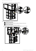
Additional safety for own arrays
When ying an array, use available holes to implement a secondary safety.
6
KARADOWNK2 rigging manual (EN) version 1.1


