


2FT
1-6-20
Yes
No
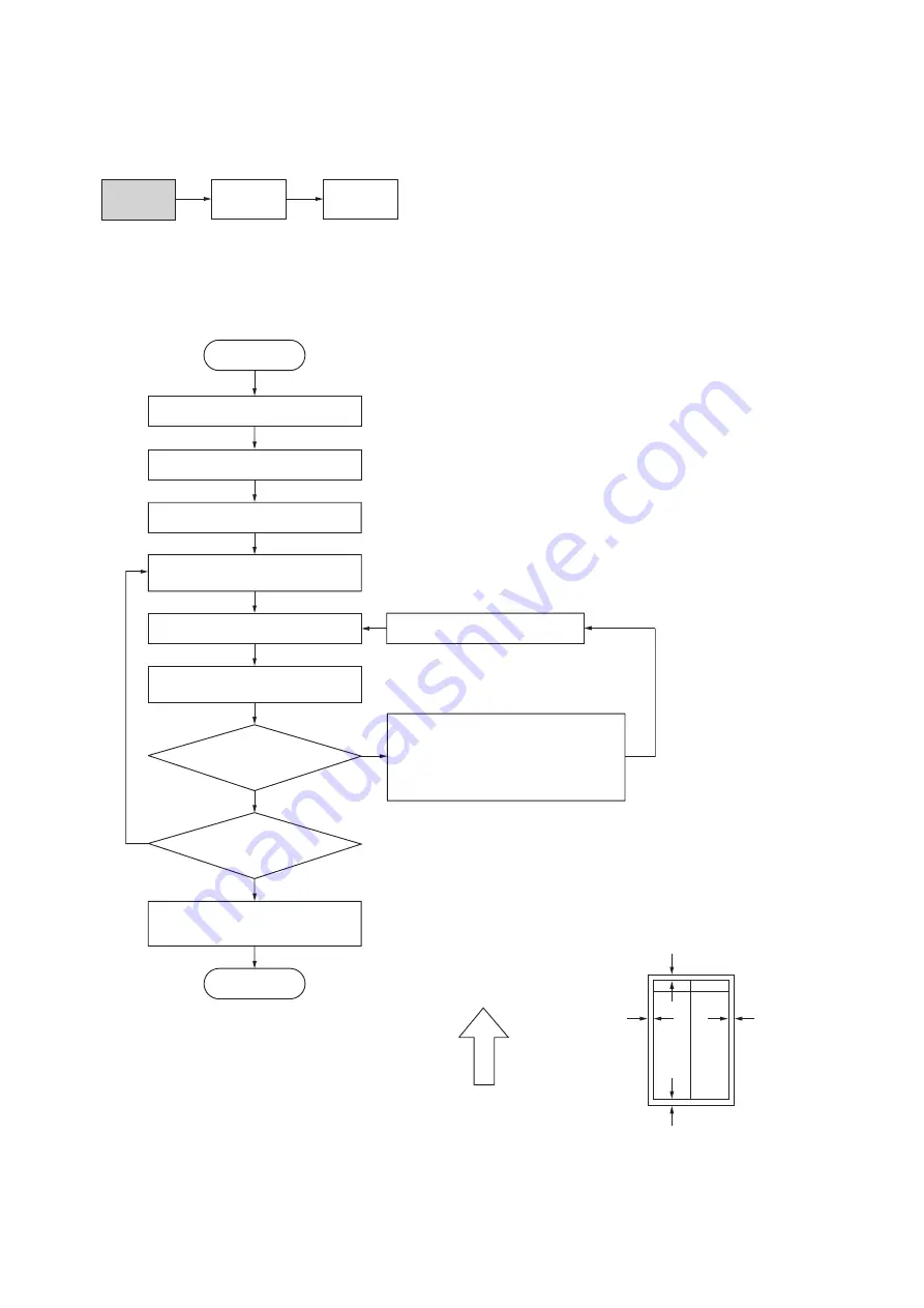
Start
Enter maintenance mode.
Enter “402” using the numeric keys.
Press the start key.
Press the start key to output a test
pattern using A3/11" x 17" paper.
Press the start key.
The new setting is stored.
Setting range (initial setting)
LEAD: 0.0 – +10.0 (3.0)
AC: –3.4 – +10.0 (3.0)
TRAIL: –5.0 – +10.0 (4.0)
Changing the value by 1 moves the
leading edge by 0.1 mm.
Select the items to be adjusted
using the up/down cursor keys.
Are the margins correct?
Change the setting.
Increasing the value using the right cursor
key makes the margin wider.
Decreasing the value using the left cursor
key makes the margin narrower.
Press the interrupt key.
LEAD: Printer leading edge margin
AC: Printer left/right margins
TRAIL: Printer trailing edge margin
Yes
No
Press the stop/clear key to
exit maintenance mode.
End
Proceed to
another mode?
(10-5) Adjusting the margins for printing
Make the following adjustment if the margins are not correct.
Caution:
Check the copy image after the adjustment. If the margins are still incorrect, perform the above adjustments in mainte-
nance mode.
Procedure
Figure 1-6-35
U402
U403
(P. 1-6-37)
U404
(P. 1-4-45)
Ejection direction
(reference)
Printer leading edge margin
(3 ± 2.5 mm)
Printer
left margin
(2.5
+1.5
mm)
Printer
right margin
(2.5
+1.5
mm)
Printer trailing edge margin
(3 ± 2.5 mm)
–2.0
–2.0
Summary of Contents for KM-2550
Page 1: ...SERVICE MANUAL Published in June 2005 842FT112 Version 3 0 KM 2550...
Page 4: ...This page is intentionally left blank...
Page 10: ...This page is intentionally left blank...
Page 123: ...2FT 1 1 4 56 This page is intentionally left blank...
Page 249: ...2FT 2 3 2 Figure 2 3 2 Power source PCB silk screen diagram 220 240 V AC 120 V AC...
Page 267: ...2FT 2 3 20 Figure 2 3 10 Operation unit PCB silk screen diagram...
Page 282: ......


