


2RG/2RH
1-4-77
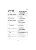
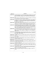
1-4-4 Electric problems
If the part causing the problem was not supplied, use the unit including the part for replacement.
Troubleshooting to each failure must be in the order of the numbered symptoms.
Problem
Causes
Check procedures/corrective measures
(1)
The machine does
not operate when
the main power
switch is turned on.
1. No electricity at the
power outlet.
Measure the input voltage.
2. The power cord is
not plugged in prop-
erly.
Check the contact between the power plug and the outlet.
3. Broken power cord.
Check for continuity. If none, replace the cord.
4. Defective main
power switch.
Check for continuity across the contacts. If none, replace
the power switch.
5. Defective power
source PWB.
Replace the power source PWB (see page 1-5-64).
6. Defective main PWB. Replace the main PWB and check for correct operation
(see page 1-5-54).
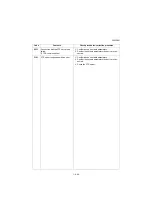
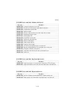
(2)
Eject motor does
not operate.
1. Defective connector
cable or poor con-
tact in the connector.
Reinsert the connector. Also check for continuity within the
connector cable. If none, replace the cable.
Eject motor and engine PWB (YC8)
2. Defective drive trans-
mission system.
Check if the rollers and gears rotate smoothly. If not,
grease the bushes and gears. Check for broken gears and
replace if any.
3. Defective motor.
Replace the eject motor.
4. Defective PWB.
Replace the engine PWB and check for correct operation
(see page 1-5-59).
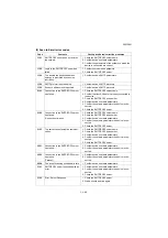
(3)
Power source fan
motor does not
operate.
1. Defective connector
cable or poor con-
tact in the connector.
Reinsert the connector. Also check for continuity within the
connector cable. If none, replace the cable.
Power source fan motor and main PWB (YC10)
2. Defective motor.
Replace the power source fan motor.
3. Defective PWB.
Replace the engine PWB and check for correct operation
(see page 1-5-59).
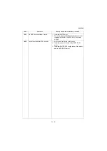
(4)
Eject fan motor
does not operate.
1. Defective connector
cable or poor con-
tact in the connector.
Reinsert the connector. Also check for continuity within the
connector cable. If none, replace the cable.
Eject fan motor and engine PWB (YC8)
2. Defective motor.
Replace the eject fan motor.
3. Defective PWB.
Replace the engine PWB and check for correct operation
(see page 1-5-59).
Summary of Contents for Copystar CS 3011i
Page 1: ...SERVICE MANUAL Published in September 2016 2RHSM 1 Rev 1 6 3011i 6 3511i ...
Page 4: ...This page is intentionally left blank ...
Page 10: ...This page is intentionally left blank ...
Page 78: ...2RG 2RH 1 2 51 B B A A B B A A B B A A Tray lower cover Pin Pin ...
Page 83: ...2RG 2RH 1 2 56 This page is intentionally left blank ...
Page 504: ...2RG 2RH 2 2 8 This page is intentionally left blank ...
Page 568: ...Installation Guide DP 7100 Document processor Installation Guide ...
Page 572: ...2 1mm 0mm ն ո պ ջ չ շ A D C B B A ...
Page 573: ...3 ռ ս վ ր ւ ց տ E A ...
Page 574: ...4 ք द I M3x8 փ F G M4x10 K J H A ...
Page 575: ...5 ON ध A ...
Page 577: ...7 շ յ ն ո D E B ...
Page 578: ...8 չ պ F G M4x10 H I M3x8 K J ջ B ...
Page 579: ...9 ռ B ...
Page 589: ...19 ո ն շ պ ջ չ 8 6 7 10 11 9 A B ...
Page 599: ...DP 7110 Document processor Installation Guide ...
Page 603: ...2 շ շ 2 շ 2 շ C M4x14 E ߑ ߒ ߓ ߔ ո շ 2 ߑ ն A ...
Page 604: ...3 ߘ ո ߕ ߗ ո չ պ ջ ߖ F G H M3x8 BLACK A ...
Page 605: ...4 ռ վ ր ւ ց ࠉտ ս I A ...
Page 606: ...5 J L փ ք द K M3x8 K M3x8 K M3x8 ध A ...
Page 607: ...6 ऩ प भ फ ब न म O N A ...
Page 608: ...7 ON य A ...
Page 610: ...9 շ ո շ 2 շ 2 շ 2 ߑ ն շ ߑ ߒ ߓ ߔ C M4x14 E B ...
Page 611: ...10 ߖ ߕ ߘ ߎ չ պ ջ ߗ F G ո H M3x8 BLACK B ...
Page 612: ...11 ռ ս տ ր ց վ I B ...
Page 613: ...12 ւ ք द ध न փ J L P K M3x8 K M3x8 B ...
Page 614: ...13 ऩ प फ O N B ...
Page 634: ...DP 7120 Document processor Installation Guide ...
Page 638: ...2 1mm 0mm ն շ ո չ ջ պ B B A D C A ...
Page 639: ...3 ռ ս վ տ ց ր E A ...
Page 640: ...4 G ւ F F ք փ H ON 10 mm 10 mm A ...
Page 642: ...6 շ ո յ ն D B ...
Page 643: ...7 չ E B ...
Page 644: ...8 F ON G պ F ջ ռ H 10 mm 10 mm B ...
Page 653: ...17 ղ ն շ ճ մ յ 2 6 7 3 4 5 A B ...
Page 655: ...19 չ ջ պ ս վ ռ 9 11 10 13 14 12 10 mm A B ...
Page 665: ...PF 791 500 x 2 Paper feeder Installation Guide ...
Page 673: ...PF 810 3000 sheet deck Installation Guide ...
Page 686: ...DF 791 3000 sheet finisher Installation Guide ...
Page 701: ...DF 7120 1000 sheet finisher Installation Guide ...
Page 705: ...2 մ յ ն 7 7 15 a b a a b b b a A ...
Page 706: ...3 ո շ չ պ A ...
Page 707: ...4 ջ ռ ս c d 14 c d c d 12 c d ջ ռ ս c d 14 c d c d 12 c d A ...
Page 708: ...5 վ ր D ց ON տ A ...
Page 710: ...7 L յ մ ն շ B ...
Page 712: ...9 ս ռ վ տ G B ...
Page 713: ...10 ր ց ւ b a 17 17 25 a b a a b b B ...
Page 714: ...11 ք փ द c d 24 c d c d 22 c d B ...
Page 715: ...12 न ध ऩ प B ...
Page 716: ...13 ब फ ON D B ...
Page 719: ...AK 740 Bridge unit Installation Guide ...
Page 721: ...MT 730 Mailbox Installation Guide ...
Page 736: ...PH 7A C D Punch unit Installation Guide ...
Page 757: ...DT 730 B Document tray Installation Guide ...
Page 759: ...5 2013 5 302LC56750 01 H F G D D 6 4 3 7 E C D D M4 8 M4 8 M4 8 M4 8 ...
Page 760: ...FAX System 12 Installation Guide ...


