


6-5
6
KC291A
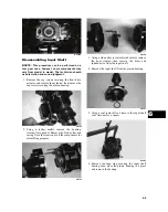
Disassembling Input Shaft
NOTE: This procedure can be performed on a
rear gear case; however, some components may
vary from model to model. The technician should
use discretion and sound judgment.
1. Remove the cap screws securing the front drive
actuator and remove the actuator; then remove the
cap screws securing the pinion housing.
CD102
2. Using a rubber mallet, remove the housing.
Account for a gasket. Remove the fork, collar, and
spring. Note the location of all the components for
assembling purposes.
CD103
CD106
3. Using a side-cutter (or suitable substitute), remove
the boot clamps; then remove the boots and
splined drive from the input shaft.
4. Remove the input shaft from the pinion housing.
CD107
5. Using a seal removal tool, remove the input shaft
seal. Account for a spacer.
AF982
6. Remove the snap ring securing the input shaft
bearing; then place the pinion housing in a press
and remove the bearing.
Summary of Contents for MXU 450i
Page 17: ...Oil level stick...
Page 23: ...Low range High range Neutral Reverse...
Page 25: ...1 mm 0 039 in...
Page 126: ...A B...
Page 127: ...LCD Gauge Connector LCD Gauge Connector...
Page 134: ...9 4 NOTES...
Page 135: ......