12 | kvm-tec
1. IntroductIon
kvm-tec | 13
2. EXTEnDEr InsTallaTIon
1.5 MEanInG of THE lED InDIcaTors
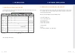
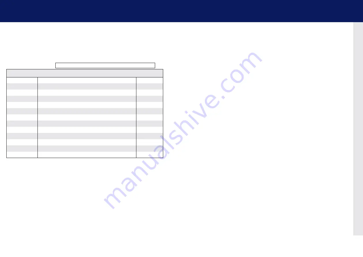
The power/status LED (14/27) can light red, orange or green. Table shows the meaning of each colour.
Also see chapter 6
Troubleshooting.
Table : Meaning of LED indicators
2.1 UnPacKInG anD cHEcKInG THE conTEnT
Before using the product for the first time it should be checked for damage. In case of damage
due to transport inform the carrier immediately. Before delivery the product is checked for its
function and its operating safety.
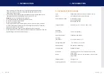
Make sure that the packaging contains the following content:
1x UVX1/local Extender CPU
1x UVX1/remote Extender CON
2x power cable IEC C13
1x DP - DP cable 1,8 m/5,9ft
1x USB A-B cable 1,8m/5,9ft
8 x mounting feets
UVX Fiber
1 x SFP+ Module-Multimode up to 300m/984ft
normal operation
* UVX only
** Rem. Only
colour
blinking Physical
link
active
connection
Video
Extended
Usb
Initialisation
Usb Data
received
Identify
command
autoupdate
Mode
Red
-
Yes
No
No
Update Failed
Red
Slow
No
No
No
Orange
-
Yes
Yes
No
Orange
Fast
Update in Progress
Green
-
Yes
Yes
Yes
Update Succedded
Green
V. fast
Yes**
Red/Green
V. fast
Yes
Yellow
-
No
Yellow
Slow
Yes
Green
-
Yes
Green
V. fast
Yes
Main lED
rJ45 socket lEDs *


