background image

Adjustments

90

Adjustments

Using the seed drill with 

the box 3.2

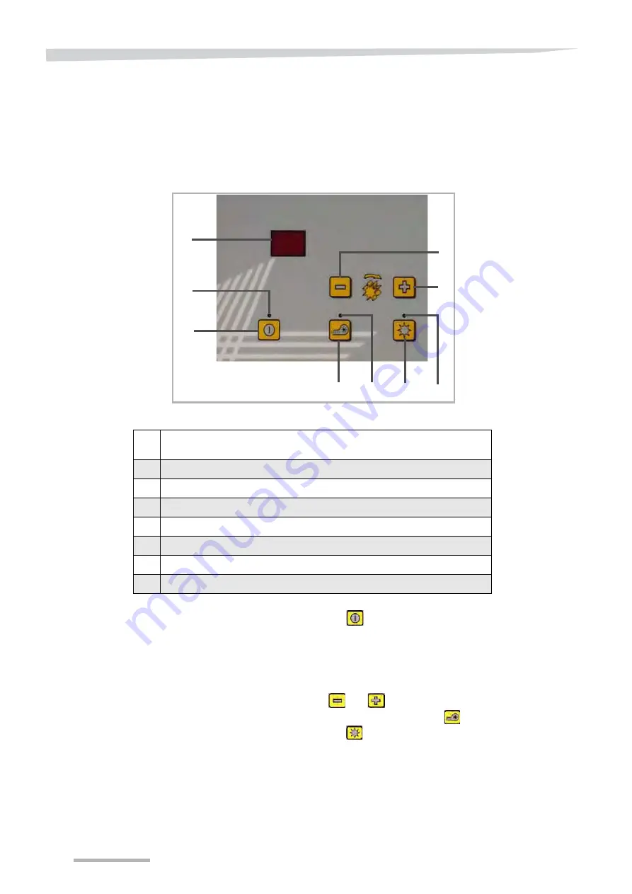
Description of the control 

module

Switching on

Press on button XX to switch on the box.

The box version is displayed.

The indicator above the button lights.

The current rotor rotation speed in percentage of its maximum 

speed is displayed.

Use buttons XX and XX to adjust the rotor rotation speed.

On electrical blowers, use the button XX to start the blower.

Press on button XX to switch on the distribution rotor.

A

B

C

D

E

F

G

H

H

A

Displays the actual rotor rotation speed as a percentage  


of its maximum speed (from 1 to 99%).

B

Box power on indicator. Lights if the box is activated.

C

"On/Off" button: Activates or deactivates the box.

D

Activates the blower (only on models with electrical blower).

E

Blower power on indicator. Lights if it is activated.

F

On / off button for the distribution rotor.

G

Rotor on indicator. Lights when the rotor is operating.

H

Rotation speed adjustment buttons for the distribution rotor.

Summary of Contents for a-drill

Page 1: ...Pneumatic seed drill a drill Operating manual Translation of the original operating manual Issue 04 2018 Printing 02 2018 Language EN From serial no RFSDCxx006315 Execution Accessories Reference RF31913 ...

Page 2: ...cturer address The copyright and use Copyright are held by the Kverneland Group Les Landes Génusson SAS France Copying transfer to other media translation or even partial use of this text are unlawful without the written authorization from Kverneland All rights reserved The content of these operating instructions may be changed without notice Subject to technical changes Kverneland Group Les Lande...

Page 3: ...mounted machines 54 Delivery and assembly 56 Qualidisc T 56 Equipment available on Qualidisc T 63 Delivery and assembly 64 CTC 64 Delivery and assembly 70 Equipment available on CTC 70 Delivery and assembly 71 Mounting kit for hopper only 71 Installing the hydraulic blower 71 Adjusting the machine 72 Lifting sensor 72 Hydraulic blower 74 Seed drill adjustment 76 Distribution 76 Filling the seedbox...

Page 4: ...e and maintenance of the machine Meaning of symbols In order to make this manual clear and easy to read we have used various symbols They are explained below A dot precedes each item in a list A triangle indicates operating functions which must be performed An arrow indicates a cross reference to other sections of this manual We have also used pictograms to help you find instructions more quickly ...

Page 5: ...ructions in the interest of your own safety in the interest of the safety of others to ensure the safety of the machine Numerous risks can result from handling agricultural machines in the wrong way Therefore always work with special care and never under pressure For the employer Inform personnel working with the machine of these safety instruc tions at regular intervals and according to statutory...

Page 6: ...ing out any operations on the machine Carrying persons on the machine while in motion in transit or at work is strictly forbidden Risk of crushing by an articulated part of the machine Install the safety devices provided and or check the working order of the automatic safety devices before entering a hazardous area Risk of hands being pinched when adjusting the machine Please follow the adjustment...

Page 7: ...h pressure cleaners directly onto the bearings the hydraulic hoses electric units or other sensitive components on the machine risk of damage The jet may bounce back off some surfaces Hydraulic system The hydraulic system is pressurised Identify the connectors using a colour code as indicated in the user manual when intervening on the hydraulic system Incorrect connections and the reversal of func...

Page 8: ...decline all liability for damage resulting from use that does not comply with the intended use The user is responsible for all risks Compliance with the conditions of use includes compliance with the manufacturer s operating instructions The safety instructions specified below as well as the general safety occupational health and road traffic regulations Modifications to the tool made by the clien...

Page 9: ...Presentation of the accessory 9 General Description A Hopper 200 or 500 l B Walkway access filling and settings C Blower electrical or hydraulic D Spreader rail in front of the roller A B C D ...

Page 10: ...cal or hydraulic blower on mounted machine hydraulic on trailed machine The box 5 2 provides the following additional services End of field sensor automatic stop and restart EFPP Electronic flow proportional to progression by radar sensor or ISO 7 terminal connector To have these two functions simultaneously the box 5 2 is equipped with a branch cable that provides 2 x 12 terminal connectors Techn...

Page 11: ...ine dummy fine dummy fb efv efv fb RF32209 Optional equipment Fine honeycomb grooves Sowing of small seeds or small quantities Eg radish mustard etc fine dummy extra fine honeycomb extra fine honeycomb fine dummy ffff A135122830 Optional equipment Fine grooves Sowing of small seeds or small quantities Eg grass wheat barley radish etc fine fine fine fine GB G GB A135132030 Optional equipment Coarse...

Page 12: ...ountings Mounting with the hopper centred compared to the machine Mounting with the hopper offset compared to the machine During offset mounting it is necessary to move it 14 cm to the left compared to the machine driving direction on the following models CLC Evo 3m00 9 10 11 tines CLC Evo 3m50 11 6 13 tines CLC Evo 4m00 13 1 15 tines ...

Page 13: ...amps fix the support to the second beam of the main frame Use the four long fixing screws Insert the 14 screws B in the tubes to fix the hopper Mounting diagrams for the platform and hopper support A B CLC 2 rows 3m00 9 10 CLC 2 rows 3m50 11 6 345 mm 13 9 16 140 mm 5 1 2 345 mm 13 9 16 A B A Platform B Hopper support ...

Page 14: ...Delivery and assembly 14 CLC 2 rows 4m00 13 1 570 mm 22 7 16 545 mm 21 1 2 CLC 3 rows 3m00 9 10 CLC 3 rows 3m50 11 6 480 mm 18 7 8 600 mm 23 5 8 CLC 3 rows 4m00 13 1 ...

Page 15: ...support arms using the fixing brackets E Using the same screws fix the guardrail and reinforcement crossbars Fix the upper part of the stairs to the extremity of the walkway Adjust the ball screws F to ensure the lower part of the stairs D is maintained on the upper part C A B C D E F A Guardrail B Reinforcement crossbar C Upper part of stairs D Lower part of stairs E Fixing brackets F Ball screw ...

Page 16: ...ry and assembly 16 Mounting diagrams for the platform CLC Evo CLC Pro 2 rows 3 rows 5 1 2 5 1 2 20 13 9 16 2 3 8 21 7 16 1 7 8 10 3 8 13 9 16 5 9 16 13 3 4 18 7 8 5 9 16 5 9 16 14 3 4 22 7 16 17 11 16 23 5 8 ...

Page 17: ...0 355 14 355 14 355 14 355 14 2257 89 2605 103 2R 3m50 arm 355 14 355 14 500 19 11 16 500 19 11 16 2757 109 3065 121 2R 3m50 470 18 1 2 430 16 15 16 450 17 11 16 450 17 11 16 2757 109 3130 123 2R 4m00 arm 525 20 11 16 525 20 11 16 525 20 11 16 425 16 11 16 3057 120 3500 138 2R 4m00 500 19 11 16 475 18 11 16 475 18 11 16 550 21 5 8 3057 120 3500 138 3R 3m00 arm 290 11 7 16 290 11 7 16 430 16 15 16 ...

Page 18: ...Delivery and assembly 18 Procedure Levelling tines fixed to the roller beam Install the rail of spreaders in the lower position on the support ...

Page 19: ...cs Fix the roller supports to the last 2 fixing holes of the parallelogram A Use and adapt the longest push bar B in order to keep the working angle of the levelling discs Use the adapting kit for machines prior to June 2012 that do not have a rear roller mounting position A B ...

Page 20: ...3m00 9 10 Offset 3335 131 3095 122 3075 121 2940 116 CLC 2R 3m50 11 6 Offset 3335 131 3095 122 3075 121 2940 116 CLC 2R 4m00 13 1 Offset 3550 140 3355 132 3645 144 3825 151 CLC 2R Wings 3m00 9 10 Centred 3195 126 2955 116 2935 116 2800 110 CLC 2R Wings 3m50 11 6 Centred 3195 126 2955 116 2935 116 2800 110 CLC 2R Wings 4m00 13 1 Centred 3410 134 3215 127 3505 138 3685 145 CLC 3R 3m00 9 10 Centred 3...

Page 21: ...arms Group the hoses and pass them in the supports Cross the hoses when you connect them to the rail of spreaders The hoses that come out of the centre of the seed drill must supply the exterior spreaders of the machine NOTE On 3 row cultivators a hose guide A is installed on the stays Mounting on parallelogram Mounting on curved arm ...

Page 22: ...s the hopper support and the access walkway are fixed to the central frame using 4 screws Procedure Align the holes located at the rear extremity of the hopper support B with the rear extremity of the central frame A of the machine Place the 4 hexagonal head M20x70 screws C in the holes Fix the screws using M20 nuts A B C D E ...

Page 23: ... onto it The hopper is placed on the support and fixed using 14 screws Procedure Place the hopper on the support fixing plate aligning the screw holes Place the 12 screws M12x30 D on the sides and rear of the hopper support Place the 2 screws M12x90 E in the holes located at the front of the hopper support Fix the screws using M20 nuts ...

Page 24: ...unted on a curved arm corresponds to a machine whose tool is mounted on a parallel ogram Procedure Levelling tines on CLC Pro Classic Adjust the rail to the low position A to position the spreaders Machine A B C D E F 4m00 490 19 5 16 530 20 7 8 530 20 7 8 530 20 7 8 3920 154 1430 56 4m00 arm 530 20 7 8 530 20 7 8 530 20 7 8 530 20 7 8 3920 154 1300 51 4m50 490 19 5 16 590 23 1 4 560 22 560 22 352...

Page 25: ...stribution for seed hoses on CLC Pro Hose 1 Hose 1 Hose 2 Hose 3 Hose 4 Hose 2 Hose 3 Hose 4 Ensure that you respect the seed outlet numbers compared to the spreader positions CLC PRO CLC PRO Classic Hose 1 Hose 1 Hose 2 Hose 3 Hose 4 Hose 2 Hose 3 Hose 4 ...

Page 26: ...ibution for seeds on CLC Evo Ensure that you respect the seed outlet numbers compared to the spreader positions Hose 4 Hose 3 Hose 2 Hose 1 Hose 4 Hose 2 Hose 1 Hose 3 CLC Evo equipped with a parallelogram CLC Evo equipped with a roller arm ...

Page 27: ...nsuring that the link is directed towards the exterior of the machine Fix the support using a metal clamping ring Attach the chain to the spring Tighten the chain so that the weight of the hoses does not make it bend Attach the chain to the link Cut the excess chain Group the hoses and fix them to the chain using plastic rings Fix the hoses to the extremity of the machine using a washer D Check in...

Page 28: ...rocedure Turn the hopper so that the hoses come out from the rear of the machine Using U clamps A fix the support to the second beam of the main frame Insert the two screws M20x160 Tighten the M20x160 screws to 500Nm torque Insert the 12 screws M12x35 B in the angles of the hopper support Place the bolts A B ...

Page 29: ...e roller beam F Position the two brackets E on the roller beam Bolt the brackets Machines equipped with double rollers Attach the walkway extension C between the platform A and the retractable step B A C D E B F A Platform B Retractable step C Walkway extension D Guardrail E Brackets F Roller beam ...

Page 30: ...mm in for the different machines 3m00 9 10 3m50 11 6 4m00 13 1 A 73 2 7 8 73 2 7 8 73 2 7 8 B 484 19 484 19 484 19 C 286 11 1 4 286 11 1 4 286 11 1 4 D 548 21 9 16 548 21 9 16 548 21 9 16 E 197 5 7 3 4 217 5 8 9 16 250 9 7 8 F 385 14 500 19 11 16 525 20 11 16 G 385 14 500 19 11 16 450 17 3 4 H 355 15 3 16 355 15 3 16 475 18 11 16 I 355 15 3 16 355 15 3 16 600 23 5 8 J 355 15 3 16 355 15 3 16 475 1...

Page 31: ... clamping ring around the 4 hoses Fix them to the machine stay A Fold the hoses ensuring that their curve is as natural as possible Pass hoses number 1 2 and 3 in a new clamping ring position C Attach this clamping ring in the furthest front hole of the drilled plate of the machine D Attach the hose number 4 to the upper part of the platform E Cross the two hoses number 4 before connecting them to...

Page 32: ...es Fix them to the machine stay A Fold the hoses ensuring that their curve is as natural as possible Attach the 4 hoses together again with a clamping ring position C Put the washer equipped with a ring on the screw in position D Attach the group of hoses to the washer clamp Check in the upper and lower positions that there are no blocking tension or crushing points for the hoses A B Hose 1 Hose 2...

Page 33: ...mbly 33 Length of hoses 3m00 9 10 3m50 11 6 4m00 13 1 Hose 1 2600 mm 102 3100 mm 122 3400 mm 134 Hose 2 2900 mm 114 2700 mm 106 2900 mm 114 Hose 3 2400 mm 94 2400 mm 94 2400 mm 94 Hose 4 2400 mm 94 2400 mm 94 2400 mm 94 ...

Page 34: ...he machine Place the 4 hexagonal head M20x70 screws C in the holes Fix the screws using M20 nuts Mounting the hopper Task description Once the support is fixed to the machine you now need to mount the hopper onto it The hopper is placed on the support and fixed using 14 screws Procedure Place the hopper on the support fixing plate aligning the screw holes Place the 12 screws M12x30 D on the sides ...

Page 35: ...dimensions mm in for the different machines A1 A2 B C1 D1 E1 F1 C2 D2 E2 F2 H1 H2 I J K L M N O P2 Q2 Q1 P1 R S T U G Disc cultivators 4m00 Marking 4m00 13 1 Marking 4m00 13 1 A1 A2 1060 42 L 155 6 1 8 B 974 38 3 8 M 306 12 C1 C2 250 9 13 16 N 209 8 1 4 D1 D2 515 20 1 4 O 20 13 16 E1 E2 515 20 1 4 P1 P2 230 9 F1 F2 480 18 7 8 Q1 Q2 315 12 3 8 G 480 18 7 8 R 1140 45 H1 H2 145 5 11 16 S 1434 56 I 15...

Page 36: ...ltivators 5m00 16 5 A1 A2 B C1 D1 E1 F1 C2 D2 E2 F2 H1 H2 I1 J1 K1 L1 G I2 M1 M2 L2 K2 J2 N O1 O2 P1 P2 Q R1 R2 S Disc cultivators 6m00 19 8 A1 A2 B C1 D1 E1 F1 C2 D2 F2 H1 H2 I1 J1 K1 L1 G I2 M1 M2 L2 K2 J2 N O1 O2 P1 P2 Q R1 R2 S E2 ...

Page 37: ...16 95 3 3 4 C1 C2 373 14 11 16 385 15 3 16 M1 M2 669 26 3 8 855 33 11 16 D1 D2 670 26 3 8 760 30 N 20 13 16 20 13 16 E1 E2 570 22 7 16 760 30 O1 O2 208 8 3 16 230 9 F1 F2 575 22 5 8 760 30 P1 P2 303 12 325 12 13 16 G 625 24 5 8 670 26 3 8 Q 1140 45 1140 45 H1 H2 218 8 9 16 240 9 7 16 R1 R2 1810 71 1940 76 I1 I2 95 3 3 4 95 3 3 4 S 5000 197 6000 236 J1 J2 278 11 290 11 7 16 ...

Page 38: ...ate F Fix with a nut Thread the rapid link support into the jack retention screw Thread the pin into the jack retention screw Place the jack retention screw into the hole located on the exterior roller arm Attach the spring C to the support B Attach the chain to the spring Attach the rapid link Tighten the chain so that the weight of the hoses does not make it bend Attach the chain to the link Cut...

Page 39: ...ach the hoses to the chain using a clamping ring F Connect the hose n 2 to the spreader Group hoses n 3 and 4 using clamping rings Attach the hoses to the chain using a clamping ring G Using clamping rings attach hose n 4 to the exterior drilled plate H of the exterior roller arm Connect the hose n 4 to the spreader Check in the upper and lower positions that there are no blocking or crushing poin...

Page 40: ...r Procedure Turn the hopper so that the hoses come out from the rear of the machine Using U clamps A fix the support to the second beam of the main frame Insert the two screws M20x160 Tighten the M20x160 screws to 500Nm torque Insert the 12 screws M12x35 B in the angles of the hopper support Place the bolts A B ...

Page 41: ...e roller beam F Position the two brackets E on the roller beam Bolt the brackets Machines equipped with double rollers Attach the walkway extension C between the platform A and the retractable step B A C D E B F A Platform B Retractable step C Walkway extension D Guardrail E Brackets F Roller beam ...

Page 42: ...g dimensions mm in for the different machines 3m00 9 10 3m50 11 6 4m00 13 1 A 187 5 7 3 8 230 9 1 16 275 10 13 16 B 187 7 3 8 187 7 3 8 187 7 3 8 C 548 21 9 16 548 21 9 16 548 21 9 16 D 187 5 7 3 8 230 9 1 16 275 10 13 16 E 395 15 1 2 465 18 5 16 555 21 7 8 F 328 13 465 18 5 16 435 17 1 8 G 402 15 13 16 392 15 7 16 435 17 1 8 H 375 14 3 4 395 15 1 2 600 23 5 8 I 402 15 13 16 392 15 7 16 435 17 1 8...

Page 43: ... that they form a square Put a clamping ring around the 4 hoses Fix them to the machine stay A Fold the hoses ensuring that their curve is as natural as possible Pass hoses number 1 2 and 3 in a new clamping ring position C Attach this clamping ring in position D Attach the hose number 4 to the upper part of the platform E Cross hoses number 4 before connecting them to the spreaders Check in the u...

Page 44: ...es Fix them to the machine stay A Fold the hoses ensuring that their curve is as natural as possible Attach the 4 hoses together again with a clamping ring position C Put the washer equipped with a ring on the screw in position D Attach the group of hoses to the washer clamp Check in the upper and lower positions that there are no blocking tension or crushing points for the hoses A B Hose 1 Hose 2...

Page 45: ...mbly 45 Length of hoses 3m00 9 10 3m50 11 6 4m00 13 1 Hose 1 2900 mm 114 3100 mm 122 3300 mm 130 Hose 2 2500 mm 98 2600 mm 102 2400 mm 94 Hose 3 2200 mm 87 2200 mm 87 2300 mm 91 Hose 4 2300 mm 91 2300 mm 91 2900 mm 114 ...

Page 46: ...ivators the hopper support and the access walkway are fixed to the central frame using 4 screws Procedure Align the holes located at the rear extremity of the hopper support B with the rear extremity of the central frame A of the machine Place the 4 hexagonal head M20x70 screws C in the holes Fix the screws using M20 nuts D E A B C ...

Page 47: ... onto it The hopper is placed on the support and fixed using 14 screws Procedure Place the hopper on the support fixing plate aligning the screw holes Place the 12 screws M12x30 D on the sides and rear of the hopper support Place the 2 screws M12x90 E in the holes located at the front of the hopper support Fix the screws using M20 nuts ...

Page 48: ...dimensions mm in for the different machines Disc cultivators 4m00 13 1 A1 B A2 C1 D1 E1 F1 G F2 E2 D2 C2 H1 H2 I J K1 K2 L M N O1 O2 P1 P2 Q R S T Marking 4m00 13 1 Marking 4m00 13 1 A1 A2 1025 40 K1 K2 155 6 1 8 B 1039 41 L 306 12 C1 C2 250 9 13 16 M 209 8 1 4 D1 D2 515 20 1 4 N 20 13 16 E1 E2 520 20 1 2 O1 O2 230 9 F1 F2 475 18 11 16 P1 P2 315 12 3 8 G 480 18 15 16 Q 1155 45 H1 H2 145 5 11 16 R ...

Page 49: ...ng 5m00 16 5 Marking 5m00 16 5 A1 A2 1025 40 L1 L2 190 7 1 2 B 1039 41 M1 M2 395 15 9 16 C1 C2 285 11 1 4 N1 N2 235 9 1 4 D1 D2 630 24 13 16 O1 O2 727 28 5 8 E1 E2 640 25 3 16 P 20 13 16 F1 F2 630 24 13 16 Q1 Q2 208 8 3 16 G 630 24 13 16 R 305 12 H 220 8 11 16 S 303 11 15 16 I 218 8 9 16 T 1155 45 J 97 3 13 16 U1 U2 1810 71 K 95 3 3 4 V 5000 197 ...

Page 50: ...O2 P1 P2 Q R1 R2 S Markin g 6m00 19 8 Marking 6m00 19 8 A1 A2 1525 60 K1 K2 665 26 3 16 B 1039 41 L1 L2 95 3 3 4 C1 C2 385 15 3 16 M1 M2 855 33 11 16 D1 D2 760 30 N 20 13 16 E1 E2 760 30 O1 O2 230 9 F1 F2 760 30 P1 P2 325 12 13 16 G 670 26 3 8 Q 1155 45 H1 H2 240 9 7 16 R1 R2 1940 76 I1 I2 95 3 3 4 S 6000 236 J1 J2 290 11 7 16 ...

Page 51: ...livery and assembly 51 Passage of hoses Order of distribution for seed hoses Ensure that you respect the seed outlet numbers compared to the spreader positions Hose 4 Hose 3 Hose 2 Hose 1 A B C F D G E F ...

Page 52: ... on the other side of the drilled plate F Fix with a nut Thread the rapid link support into the jack retention screw Thread the pin into the jack retention screw Place the jack retention screw into the hole located on the exterior roller arm Attach the spring C to the support B Attach the chain to the spring Attach the rapid link Tighten the chain so that the weight of the hoses does not make it b...

Page 53: ...hoses using clamping rings Group the 3 hoses in position E and fix them to the chain using clamping rings Connect the hose n 2 to the spreader Group hoses n 3 and 4 in position F and attach them to the chain using clamping rings Connect the hose n 3 to the spreader Fix hose n 4 to the oblong hole in the exterior roller arm G using a clamping ring Connect the hose n 4 to the spreader G F ...

Page 54: ...that the tractor upper link activates the sensor when the machine is raised Attach all Radar sensor B The radar system allows you to adapt the seed distribution flow to your tractor speed Position the bracket on the front beam of the frame Insert the plate onto the bracket Position the washers and fix all Ensure that no objects cables hoses coupling bar etc enter the radar detection field A B Neve...

Page 55: ...you to adapt the seed distribution flow to your tractor speed Install the radar support on the reinforcement plate located under the front beam of the frame Fix the support using 4 M8x16 bolts Install the radar on the support Fix the radar using 4 M8x16 bolts Rigid and folding machines Tractor speed information cable The rotor distribution speed can also be communicated to the control box via a 7 ...

Page 56: ...this way the seed drill is always horizontal whether the machine is lowered or raised Procedure Turn the hopper so that the hoses come out from the front of the machine Place the hopper on the support Align the fixing holes Position the 10 nuts M12x80 A on the sides of the support Place the 4 screws M12x30 B at the front and rear of the support Fix all to the recommended tightening torques A B ...

Page 57: ...y Adjustments to the seed drill are carried out either by the walkway or the ground by the rear of the machine Procedure Mount the walkway on the hopper support Position the 4 screws M16x90 A in the holes provided Fix the M16x90 screws Install the 2 guardrails Position the 8 brackets B in the holes provided Fix the brackets using M8x8 nuts C A B C ...

Page 58: ...ection of the spreaders is optimal when the hoses are in contact with the roller beam The following diagrams and tables specify the mounting dimensions mm in for the different machines Diagrams Compact trailed discs cultivator 4m00 13 1 A1 B A2 C1 C2 D E F1 F2 G1 G2 H1 H2 I1 J1 K1 L1 M L2 K2 J2 I2 N O Marking 4m00 13 1 Marking 4m00 13 1 A1 A2 1060 42 I1 I2 250 9 13 16 B 1024 40 5 16 J1 J2 515 20 5...

Page 59: ...1 G2 H I J1 K1 L1 M1 N M2 L2 K2 J2 O P Marking 5m00 16 5 Marking 5m00 16 5 A1 A2 1060 42 I 217 8 1 2 B 1024 40 J1 J2 362 5 14 1 4 C1 C2 88 3 7 16 K1 K2 675 26 1 2 D1 D2 1120 44 L1 L2 575 22 5 8 E 263 10 3 8 M1 M2 575 22 5 8 F 213 8 3 8 N 625 26 3 8 G1 G2 350 13 3 4 O 20 3 16 H 357 14 P 5000 197 ...

Page 60: ... C2 I1 J1 F1 G1 K1 L1 H G2 F2 L2 K2 J2 I2 M N Marking 6m00 19 8 Marking 6m00 19 8 A1 A2 1590 63 H 20 3 16 B 1024 40 I1 I2 385 16 3 16 C1 C2 1350 53 J1 J2 750 29 1 2 D1 D2 323 12 3 4 K1 K2 750 29 1 2 E1 E2 265 10 7 16 L1 L2 750 29 1 2 F1 F2 360 14 3 16 M 730 28 3 4 G1 G2 540 21 1 4 N 6000 236 ...

Page 61: ... I1 J1 F1 G1 K1 L1 H G2 F2 L2 K2 J2 I2 M N Marking 7m00 22 12 Marking 7m00 22 12 A1 A2 1590 63 H 20 3 16 B 1024 40 I1 I2 370 14 1 2 C1 C2 1700 67 J1 J2 875 34 7 16 D1 D2 358 14 1 16 K1 K2 945 37 3 16 E1 E2 265 10 7 16 L1 L2 945 37 3 16 F1 F2 500 19 11 16 M 730 28 3 4 G1 G2 575 22 5 8 N 7000 276 ...

Page 62: ... bracket B on the roller arm Mount the hose support A on the bracket Bolt the hose support to the bracket Ensure that you respect the seed outlet numbers compared to the spreader positions Hose 1 Hose 2 Hose 3 Hose 4 4m00 13 1 5m00 16 5 6m00 19 8 7m00 20 12 Hose 1 3110 122 3140 134 3780 149 4275 168 Hose 2 2750 108 2880 113 3200 126 3475 137 Hose 3 2250 89 2345 92 2510 99 2675 105 Hose 4 2045 81 2...

Page 63: ... is an inductive type sensor and detects the sliding rod B fixed on the jack When the rod leaves the detection range of the sensor the seed drill distribution is cut off Radar sensor The radar system allows you to adapt the seed distribution flow to your tractor speed Tractor speed information cable The rotor distribution speed can also be communicated to the control box via a 7 terminal cable How...

Page 64: ... hopper support Task description The hopper support is fixed to the rear of the central frame Procedure Position the hopper support to the rear of the central frame of the machine Insert the 6 screws M20x70 in the holes provided Fix the 6 screws using M20 bolts A B ...

Page 65: ...e recommended tightening torques Mounting the walkway Task description The seed drill is accessed from the rear of the machine via the stairs and the walkway Adjustments to the seed drill are carried out either by the walkway or on the ground by the rear of the machine Procedure Mount the walkway on the hopper support Position the 4 screws M16x40 A in the holes provided Place the nuts M16 on the s...

Page 66: ...al when the hoses are in contact with the roller beam The following diagrams and tables specify the mounting dimensions mm in for the different machines Diagrams A1 A2 B1 B2 C1 C2 D1 D2 E1 E2 F1 G1 H1 I H2 G2 F2 J Trailed tine cultivator 4m00 13 1 Marking 4m00 13 1 Marking 4m00 13 1 A1 A2 100 3 15 16 F1 F2 550 21 5 8 B1 B2 115 4 1 2 G1 G2 550 21 5 8 C1 C2 247 9 3 4 H1 H2 430 16 15 16 D1 D2 497 19 ...

Page 67: ...d tine cultivator 6m00 19 8 A1 A2 B1 C1 C2 B2 D1 D2 E1 E2 F F F F F F G F Marking 5m00 16 5 6m00 19 8 Marking 5m00 16 5 6m00 19 8 A1 A2 100 3 15 16 100 3 15 16 E1 E2 1250 49 497 19 9 16 B1 B2 97 3 13 16 277 10 15 16 F 630 24 13 16 755 29 3 4 C1 C2 215 8 7 16 1100 43 G 5000 197 6000 236 D1 D2 497 19 9 16 48 1 7 8 ...

Page 68: ...ort on the interior arm ensuring that the link is directed towards the exterior of the machine Fix the support using a metal clamping ring Attach the chain to the spring Tighten the chain so that the weight of the hoses does not make it bend Attach the chain to the link Cut the excess chain Ensure that you respect the seed outlet numbers compared to the spreader positions Hose 4 Hose 3 Hose 2 Hose...

Page 69: ...s to the chain using clamping rings Connect the hose n 3 to the spreader Group the 2 remaining hoses in position B Attach the 2 hoses to the chain using clamping rings Connect the hose n 2 to the spreader Attach the hose n 4 in position C Attach the hose n 4 to the screw located on the drilled plate using a washer M16 D Connect the hose n 4 to the spreader D ...

Page 70: ...d drill distribution is cut off Radar Sensor The radar system allows you to adapt the seed distribution flow to your tractor speed Tractor speed information cable The rotor distribution speed can also be communicated to the control box via a 7 terminal cable However your tractor must be equipped with a 7 terminal speed information socket A B Never look directly at the radar detection head when ope...

Page 71: ...machine Turn the hopper so that the hoses come out from the front of the machine Place the hopper on the support Align the fixing holes Place the 14 screws M12x30 Bolt all to the recommended tightening torques Position the spreaders on your machines Connect the distribution hoses to the spreaders Installing the hydraulic blower In order to supply oil to the hydraulic blower Connect a hose to the T...

Page 72: ...on signal to the seed drill which stops all seed distribution Mount the support plate A on the coupling head of the machine Fix all Rigid machines Insert the nut M24x8 and bolt Folding machines Insert the nuts M8x35 and bolt Position the sensor detection rod C under the upper link bar Rigid Folding A B C D1 D2 B C A Sensor support plate B Lifting sensor C Sensor detection rod D1 Nut M24x8 D2 Nuts ...

Page 73: ...detection rod is located on the jack rod By default when the rod passes in front of the sensor the seed drill stops the distribution CTC Qualidisc T A B E C D F A Sensor support plate B Inductive sensor C Clamping ring D Rod support E Rod F Default factory values A B C D A Inductive sensor B Sensor support plate C Rod support D Default factory values ...

Page 74: ... the blower rotation speed in case of reduction in tractor engine speed or operation of other hydraulic functions A A The adjustment of the hydraulic blower is an important task that must be carried out carefully Failure to respect the following instructions could lead to machine damage The adjustment must be as precise as possible to avoid sowing defects in case of low revving or damage to the bl...

Page 75: ...aximum A On the tractor flow regulator adjust the oil level to 0 Switch on the blower Slowly increase the oil quantity in order to bring the blower to the required rotation speed Ensure that you do not exceed 80L minute If the tractor produces more oil the system risks overheating particularly if the tractor does not have an oil cooling system ...

Page 76: ... of distribution rotors page 11 to choose the most suitable rotor To replace the distribution rotor proceed as follows Fully empty the hopper Unscrew the two nuts A Remove the side cover B Remove the agitator drive belt C Unscrew the knurled nuts from the rotor bearing Remove the distribution rotor D and the bearing E Install the new distribution rotor Carry out the reverse procedure to re mount A...

Page 77: ...oid damaging the distribution wheels when sowing large seeds Vetch peas beans etc We also recommend using Flex distribution rotors as these are flexible and do not break Procedure Unscrew the two knobs A Remove the sheet Unscrew the 4 Allen screws M6x12 B Remove the hopper bottom sheet A B ...

Page 78: ...owing of large seeds is likely to cause blocking of the agitator To avoid this it is necessary to remove the drive belt located under the protection cover on the side of the seed drill To remove the drive belt follow this procedure Fully empty the hopper Unscrew the two nuts located on the side cover Remove the side cover Remove the agitator drive belt Hopper level sensor This sensor equips 500L 1...

Page 79: ...ty sown for different seeds in kilogrammes per minute quantity returned during a fixed position flow test The table values can be used as close values Numerous factors such as the specific weight weight of a thousand seeds seed humidity modification to fluidity etc can lead to differences with these values The fixed position flow tests allow these differences to be corrected To determine the requi...

Page 80: ...Seed drill adjustment 80 Sowing tables ...

Page 81: ...Seed drill adjustment 81 ...

Page 82: ...Seed drill adjustment 82 ...

Page 83: ...Seed drill adjustment 83 ...

Page 84: ...Seed drill adjustment 84 ...

Page 85: ...Seed drill adjustment 85 ...

Page 86: ...he adjustment graphs tighten to the maximum the knob located on the hydraulic unit Loosen the number of turns indicated on the graph Sowing width of 3m00 and 3m50 9 10 and 11 6 Description Seed cate gory Description Seed cate gory Rapeseed 1 Physiostart 2 Poppy 1 Buckwheat 2 Alfalfa 1 Barley 2 Red clover 1 Green rye 2 Mustard 1 Wheat 2 Phacelia 1 Vetch 3 Radish 1 Peas 3 Grass 1 Beans 3 Oats 1 Fert...

Page 87: ...th of 6m00 19 8 4Kg min in category 1 tighten the valve to the maximum then loosen 5 turns 0 0 2 1 4 6 8 10 12 14 16 18 20 22 24 26 2 3 4 5 6 7 8 9 10 Hydraulic adjustment number of turns Seed dosage Kg min 1 2 3 0 0 2 1 4 6 8 10 12 14 16 18 20 22 24 26 2 3 4 5 6 7 8 9 10 Hydraulic adjustment number of turns Seed dosage Kg min 1 2 3 ...

Page 88: ...88 Filling the seedbox Safety Folding CLC Fold the machine to get to the seedbox Fill in the seedbox In order to avoid any accident make sure the machine is on the ground before filling the seedbox A B A CLC PRO B CLC EVO ...

Page 89: ...Filling the seedbox 89 Qualidisc and Qualidisc Farmer Unfold the machine Fill in the seedbox ...

Page 90: ...e the button XX to start the blower Press on button XX to switch on the distribution rotor A B C D E F G H H A Displays the actual rotor rotation speed as a percentage of its maximum speed from 1 to 99 B Box power on indicator Lights if the box is activated C On Off button Activates or deactivates the box D Activates the blower only on models with electrical blower E Blower power on indicator Ligh...

Page 91: ... adjustments and carry out the distribution according to your requirements Unscrew the two knobs A located on the distribution sheet B Re install the lower plate C to accentuate its slope Attach the lower plate in position on the frame using the knob D located to the right Place a bag or recipient at the extremity of the distribution sheet to recover the seeds Using the formula given in section Wo...

Page 92: ...e battery Check the cabling Check the tractor alternator 02 The box operating voltage is too high Check the tractor alternator 03 The internal voltage is insufficient Return the box to the factory 04 The distribution rotor is blocked or the motor has suffered an overload Stop the box Check if materials or solid objects prevent the rotation of the distribution rotor block the agitator or affect the...

Page 93: ... the box Problem Possible solution Having pressed on button XX nothing is displayed on the box Check whether the power supply cable is correctly plugged into the box Check whether the box cable is connected to the correct battery terminals Incorrect connection to the battery terminals or defective connections can cause damage to the box ...

Page 94: ...wer When starting the indicator flashes If the blower operates continuously the indicator remains lit Hydraulic blower The indicator lights as soon as the blower has generated enough pressure E Blower power on indicator Lights if it is activated F On off button for the distribution rotor G Rotor on indicator Lights when the rotor is operating H Rotation speed adjustment buttons for the distributio...

Page 95: ...Adjustments 95 Main display Organisation of the menus ...

Page 96: ...el speed in kilometres per hour can be adjusted in the menu tab Distribution Test km h 10 0 20 0 SW 25 0 50 A B Set point value A Real value B RA Distribution rotor rotation speed defined as a percentage of the maximum rotor speed Use the buttons XXX and XXX to adjust this parameter Real distribution rotor rotation speed as a percentage of its maximum speed The rotation speed is calculated by the ...

Page 97: ...stribution it is essential to carry out a distribution test This test allows you to refine your adjustments and carry out the distribution according to your requirements Menu tab In addition to the distribution test this tab also allows you to adjust certain general values Distribution rotor rotation speed working width travel speed The entered values are respected during the calculation of the so...

Page 98: ... that you wish to sow Enter the duration of the distribution test 5 If all values are correctly adjusted launch the test 6 The test starts 7 The rotor turns automatically without the blower At the end of the defined time the rotor stops automatically On 500 L seed drills or if a hopper level sensor is mounted the message Recipient almost empty may appear but the test will still carry on The lack o...

Page 99: ...d automatically The display returns to the main menu Hectare counter Displays in hectares ha the total surface and sown surface since the start of work The calculation values are automatically adjusted after the distribution test refer to section Distribution Test page 97 The counter starts as soon as the distribution rotor starts turning To reset the Surface tab to zero press on the button XX for...

Page 100: ...box choose the tab Speed calibration Press on XX to select this tab Choose the tab Calibration distance 100m Press on XX Press on XX to start the test and begin to advance Having travelled 100 metres 328 press on XX to stop the calibration The following message is displayed when the calibration is finished The number of radar impulsions on the ground during the 100 metres is displayed Note this nu...

Page 101: ...ox has been reset follow the procedure below In the main menu of the box choose the tab Speed calibration Press on XX to select this tab Choose the tab Calibration value Enter the number of impulsions over 100 m 328 obtained during the previous calibration Validate Resetting the calibration This function resets the calibrated value to its factory configuration In the main menu of the box choose th...

Page 102: ...isplayed on the counter correspond to the total and daily operating duration of the distribution rotor The counter starts as soon as the distribution rotor starts turning To reset the hour tab to zero press on the button XX for 5 seconds The Total hours tab cannot be reset to zero Operating voltage and current intensity This screen displays the operating voltage and current intensity in the blower...

Page 103: ...n XX to validate the selection Seed drills equipped with a hydraulic blower Wait until the message Motor not connected is displayed Press on XX You have 15 seconds to select the required language Press on XX to validate the selection Changing the flow during operation The flow can be increased or decreased to a maximum of 50 Press or to increase or decrease the flow Language Langue Sprache ...

Page 104: ...speed calibration is too high Reduce the number of magnets on the wheel sensor If this does not work contact the After Sales Service The number of impulsions between the radar and the ground during speed calibration is too low Increase the number of magnets on the wheel sensor If this does not work contact the After Sales Service Appears when the speed of the distribution shaft is too low during c...

Page 105: ...onger at least 20 seconds The driving speed is too high Compare with the pre defined adjustments Adjust your speed The driving speed is too low Compare with the pre defined adjustments Adjust your speed Screen displayed when the box stops Display Cause Solution Tractor speed too high Tractor speed too low i Switch off ...

Page 106: ...rvice Appears when the hydraulic turbine does not produce any air flow or when the return pressure in the motor tank pipe of the hydraulic turbine is too high Start the hydraulic turbine Replace the return filter Do not use a reducer in the tank pipe Use a larger tank pipe Appears when the hydraulic turbine is not activated The pressure sensor is not actuated by the air flow Check the cabling Chec...

Page 107: ...eck the cables for damage and short circuits Appears if The motor is connected The motor is not overloaded The motor is not running Contact After Sales Appears if The cables are not connected The cables are faulty Check the cables Check the connectors Appears if The spreader plate cannot turn The motor is loaded in the limit range for too long Stop the appliance Check whether any foreign bodies ar...

Page 108: ...ge the position of the sensor The speed sensor does not send any information The speed sensor is not detected Incorrect selection of the speed sensor The cable is incorrectly connected or faulty Connect the cable correctly according to the markings No signal from the lifting mechanism sensor The lifting mechanism sensor is not detected The lifting mechanism does not send a signal to the 7 pole sig...

Page 109: ...hes when working The grain properties have changed Check the surface counter Check the working speed Calibrate the speed sensor Check the sensor of the lifting mechanism Perform a calibration Reduce the speed of the hydraulic turbine Return pressure too high Pipe cross section too small The pipe is too long Return filter clogged Use a larger pipe cross section Reduce the length of the pipe Use a n...

Page 110: ...aintenance work Carry out maintenance work only if you have the necessary knowledge and if you have appropriate tooling A lack of knowledge or inappropriate tools may lead to accidents Use original spare parts Use only original spare parts for components related to safety Dimensions stability and material quality must be in conformity If parts other than original parts are installed the guarantee ...

Page 111: ...Claims must be made in writing within 6 days The guarantee will be granted only if the conditions appearing on the delivery contract have been met by the buyer The guarantee cannot be granted if the accessory was repaired by the client without the dealer s agreement was modified by the installation of components other than original parts ...

Page 112: ...on the ground or pour into the sewers used grease or other substances such as motor oil hydraulic oil coolant fluid brake fluid fuel Metal parts All metal machine components can be sent to scrap recycling Hydraulic oil Collect hydraulic oil in watertight clean containers designed for this purpose Avoid using food containers or drink bottles Take hydraulic oil and hoses to a suitable recycling cent...

Page 113: ...stipulated in the European directive 2006 42 EC For the relevant implementation of the safety and health requirements mentioned in the EC Directive the following standards have been taken into account Kverneland Group Les Landes Génusson Les Landes Génusson on 02 07 2012 Kverneland Group Les Landes Génusson S A S 9 Rue du Poitou 85130 LES LANDES GENUSSON FRANCE Les Landes Génusson 02 11 2013 Hasan...

Page 114: ... level sensor 98 Hydraulic blower 71 74 94 Hydraulic oil 112 Hydraulic supply 10 Hydraulic system 7 Hydraulic unit 71 74 86 I Intensity current 102 L Languages 103 M Main display 95 Main menu 97 98 99 100 101 102 103 Maximum pressure 10 Metal parts 112 Mounted machines 54 72 O Operating voltage 92 102 104 106 P Pictograms 4 6 pictograms 6 Platform 29 31 41 43 Pneumatic seed drill 10 Q Qualidisc 28...

Page 115: ...bution 96 97 98 99 Tractor speed information cable 55 63 70 71 Trailed machines 73 Type of Seed drills 10 U User 6 safety 5 6 User safety 5 V Version 3 2 10 Version 5 2 10 Voltage operating 102 104 106 W Walkway 9 15 29 34 41 46 57 65 ...

Reviews: