background image

Kvaser Eagle User's Guide


19(30)


Kvaser AB, Mölndal, Sweden 

— www.kvaser.com 


6  Appendices 

In this section, you will find technical information about Kvaser Eagle and its connectors. 
 

6.1 

Technical Data 

 
In Table 5 below, 

you will find the Kvaser Eagle’s technical specifications. 

Table 5: Kvaser Eagle Technical Specifications 

CAN Channels 

2 (CAN 2.0A and 2.0B active) 

CAN Transceivers (HS) 

SN 65251 (Compliant with ISO 11898-2) 

CAN Controller 

Built into the processor 

CAN Bit Rate 

50 kbit/s to 1 Mbit/s 

Error Frame Detection 

Both channels 

Error Frame Generation 

Available when used as an USB-CAN interface 

PC interface 

USB 2.0; Supports HiSpeed (HS) at 480 Mbit/s 
Compatible with USB 1.1 at 12 Mbit/s and with USB 3.0 at 480 Mbit/s 

Power consumption 

Typical values are: 
150 mA if powered from the USB (~ 5V) 
900 mW when powered from the CAN bus 

External power 

Allowed operating voltage 7-35 V DC 
Absolute maximum input voltage 48 V DC 

Software requirements 

Windows XP or later 
(For other operating systems, see Kvaser web or contact support.) 

Hardware configuration 

Done by software (Plug & Play) 

Dimensions (W x L x H) 

46 x 115 x 22 mm (1.8 x 4.5 x 0.9 inch) 

Operating temperature 

-40 ºC ... +85 ºC 

Weight 

142 g including cables and connectors 

Storage temperature 

-40 ºC ... +85 ºC 

Relative Humidity 

0% ... 85% (non-condensing) 

External trigger 

Available on CAN connector 1 pin 4 

External output 

Available on CAN connector 2 pin 4 


Summary of Contents for Eagle

Page 1: ...2 We believe that the information contained herein was accurate in all respects at the time of printing Kvaser AB cannot however assume any responsibility for errors or omissions in this text Also note that the information in this document is subject to change without notice and should not be construed as a commitment by Kvaser AB ...

Page 2: ...Kvaser Eagle User s Guide 2 30 Kvaser AB Mölndal Sweden www kvaser com This page is intentionally left blank ...

Page 3: ...er Output 15 5 How to Use the Kvaser Eagle 17 5 1 Kvaser Memorator Tools 17 5 2 Disk Management 17 5 3 Use as a CAN Interface 17 5 4 Configure for Logging 18 5 5 Use as a Logger 18 5 6 Using the Kvaser t Programming Language 18 5 7 Troubleshooting 18 6 Appendices 19 6 1 Technical Data 19 6 2 Performance 20 6 3 Disk Capacity 20 6 4 Disk Structure 21 6 5 CAN Connectors 21 6 6 Updating the Firmware 2...

Page 4: ...manual is intended for Kvaser Eagle users It contains a description of the hardware s properties and general instructions for connecting the device to a computer The setup software for the Kvaser Eagle is called the Kvaser Memorator Tools and is described in detail in the application s online help ...

Page 5: ...er t language for even more advanced setups A standard SD flash disk is included These memory cards are robust inexpensive and small about the size of a stamp Kvaser Eagle can also be used as a powerful two channel real time CAN to USB interface 3 1 1 Triggers Log continuously or create triggers to control when frames are logged You can create up to 32 trigger conditions These conditions can inclu...

Page 6: ...ess Some examples include writing more advanced filters simulating one or more CAN nodes and creating a standalone ECU re flash unit For more information about t see The Kvaser t Programming Language 3 2 Major Features of Kvaser Eagle CAN interface data logger and Kvaser t programmability three products in one Quick and easy plug and play installation Supports both 11 bit CAN 2 0A and 29 bit CAN 2...

Page 7: ...enecks Handles up to 40 000 messages per second Supports silent mode for analyzing tools listen to the bus without interfering Simultaneous operation of multiple devices Power supplied through the CAN bus interface or through the USB interface 3 5 Kvaser Memorator Tools Easy to use graphic configuration tool File manager for organizing and converting log files to several formats including CSV ASCI...

Page 8: ...vaser Eagle Software and Documentation CD contains Windows drivers Kvaser Memorator Tools configuration tool Kvaser CANKing easy to use CAN bus monitor Drivers for RP1210A LabView and DIAdem Kvaser CANlib Software Development Kit Kvaser Eagle User s Guide The Kvaser t Programming Language USB cable SD card 4 2 USB Connector The Kvaser Eagle has a standard USB type B receptacle connector Connect th...

Page 9: ...e Kvaser Eagle 4 4 Power Supply The Kvaser Eagle can be powered from the CAN side and from the USB side To operate the Kvaser Eagle in logger mode you must supply power on the CAN side When you supply power on the CAN side provide power on the channel 1 connector Use pin 9 for V and pin 3 for ground Supplying power on channel 2 is safe but will not affect the unit 4 4 1 Kvaser Eagle ...

Page 10: ...gital High Capacity disks SD Secure Digital or MMC MultiMediaCard disks with your Kvaser Eagle The following disk sizes can be used Table 1 Usable Disk Sizes MMC 32 MB 1 GB SD 32 MB 2 GB SDHC Up to 32 GB 4 5 2 Write Protection Switch The Kvaser Eagle will disregard the write protection switch setting on SD and SDHC memories This is by design The intention is to minimize the risk of a logging failu...

Page 11: ...Eagle is being used as a CAN interface or as a CAN logger The following tables describe how the LEDs behave in these two cases Table 2 LED Indicators Overview Lamp General meaning PWR Green Power and general status CAN 1 Yellow Status for CAN channel 1 CAN 2 Yellow Status for CAN channel 2 ERR Yellow and red Indicates temporary and permanent errors Note that the ERR lamp is bi colored and can be b...

Page 12: ... ERR Red Meaning Slow flash Waiting for USB connection with the PC Steady Power ON Device is connected to the computer Short flash CAN traffic on channel 1 Short flash CAN traffic on channel 2 Short flash Error frame on either channel Steady Self test failed wrong bit rate CAN bus transceiver failure Fast flash Firmware configuration error should not normally happen contact support ...

Page 13: ...t support Logging status PWR 90 on and 10 off Everything OK logging started without problems The device is armed and waiting for a trigger PWR flashing Everything OK logging is active and actively logging traffic PWR blinking slowly 50 50 Logging has stopped due to a trigger condition and the Kvaser Eagle is off bus When connected to Kvaser Memorator Tools Running lights Device is communicating wi...

Page 14: ...connector and ground which can be found on pin 3 of the same connector See Figure 7 Connect a signal between 0 and 5 V to pin 4 of the CAN channel 1 connector Internally pin 4 of the CAN channel 1 connector has a pull up to 5V See Figure 6 The trigger can be configured to react on either falling or rising edges If it is set to trigger on a falling edge the trigger is activated when pin 4 is connec...

Page 15: ...nced by the firmware A pulse with length shorter than approximately 30 ms will not be detected 4 8 External Trigger Output The Kvaser Eagle also supports sending an external pulse through channel two s CAN connector pin 4 For further information on how to configure the Kvaser Eagle to send an external pulse refer to the Kvaser Memorator Tools online help ...

Page 16: ...Kvaser Eagle User s Guide 16 30 Kvaser AB Mölndal Sweden www kvaser com Figure 8 Trigger Output Inside the Kvaser Eagle Figure 9 Sample Circuit for Connecting a LED to the Trigger Output ...

Page 17: ...care They are robust but better safe than sorry Avoid removing the disk when the device is powered You should first disconnect external power and wait for the PWR LED to go out then remove the disk If the device is connected via USB you should make sure the Kvaser Memorator Tools is not writing to the disk before removing You may remove and reconnect the disk the external power and the USB in any ...

Page 18: ...nd dark 10 of the time If CAN traffic is detected the CAN1 and CAN2 lamps will be illuminated 5 6 Using the Kvaser t Programming Language The Kvaser Memorator Tools is used for downloading Kvaser t scripts to the device See The Kvaser t Programming Language for more information about using Kvaser t 5 7 Troubleshooting Use Kvaser Hardware in the Control Panel to verify that the computer can communi...

Page 19: ...ce PC interface USB 2 0 Supports HiSpeed HS at 480 Mbit s Compatible with USB 1 1 at 12 Mbit s and with USB 3 0 at 480 Mbit s Power consumption Typical values are 150 mA if powered from the USB 5V 900 mW when powered from the CAN bus External power Allowed operating voltage 7 35 V DC Absolute maximum input voltage 48 V DC Software requirements Windows XP or later For other operating systems see Kv...

Page 20: ...ers SD memory size support 2 GB SDHC memory support 32 GB Galvanic isolation Yes Number of triggers 32 6 3 Disk Capacity The following table gives some approximate values for the capacity of various disk sizes Table 7 Disk Capacity Disk size Capacity Time to fill the disk at 500 messages per second 32 MB 1 million messages half an hour 512 MB 10 million messages half a day 4 GB 100 million message...

Page 21: ...he structure and position of the files must be determined by the firmware or data logging will fail Do not touch these files using an ordinary flash disk writer Kvaser Memorator Tools will create the following files on the flash disk when formatting LOGDATnn KMF PARAM LIF DATABASE BIN The LOGDATnn KMF will by default occupy nearly the whole disk regardless of whether the file contains any logging ...

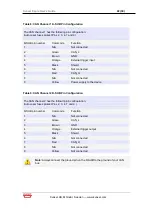
Page 22: ... 5 Black Shield 6 N A Not connected 7 Red CAN_H 8 N A Not connected 9 Yellow Power supply to the device Table 9 CAN Channel 2 D SUB Pin Configuration The CAN channel 2 has the following pin configuration Auto reset fuses protect Pins 2 3 4 7 and 9 D SUB pin number Color code Function 1 N A Not connected 2 Green CAN_L 3 Brown GND 4 Orange External trigger output 5 Black Shield 6 N A Not connected 7...

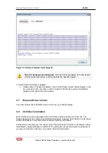
Page 23: ...r Eagle firmware by the click of a button see the online help if you want to learn more A small application opens where you should see the device listed if correctly connected to your PC see Figure 11 Select the device to program and click the Next button Figure 11 Firmware Update Select Device Click on the Start Upgrade button to start programming see Figure 12 The programming typically takes app...

Page 24: ...ears in the right half of the window 6 7 Required Driver Version You need at least driver CANlib version 4 6 to use your Kvaser Eagle 6 8 CAN Bus Termination Every CAN bus must be terminated with a 120 Ohm resistor at each end of the bus The Kvaser Eagle does not contain any CAN bus terminators because their inclusion could cause severe disturbance in a system which is already correctly terminated...

Page 25: ...file formats To avoid losing important messages during logging filters can be used This will decrease the load on the Kvaser Eagle and ensure that important information is not lost 6 10 Daisy chaining Several Interfaces You can daisy chain several Kvaser Eagle units to gain additional logging capacity To do this 1 Connect the trigger output of one device to the trigger input of the next device 2 U...

Page 26: ...on the CAN bus load To get a feeling for the numbers involved see section Disk Capacity on page 20 Q Can I use 2 4 8 16 GB disks A Yes the largest supported disk size is 32 GB Q Can I use any MMC SD SDHC disk A Yes in principle but due to the high demands placed on the SD card used by an industrial product such as the Kvaser Eagle we can only support cards tested and sold by Kvaser see section 4 5...

Page 27: ...tion When this product reaches its end of life dispose of it according to your local environmental laws and guidelines Dispose of batteries according to your local environmental laws and guidelines For information about Kvaser s recycling programs visit http www kvaser com en kvaser environment recycling ...

Page 28: ... MAY RESULT FROM THE ACTIVITY OR NON ACTIVITY OF SOME DISTRIBUTED EMBEDDED SYSTEM FUNCTIONS AND OPERATIONS WHICH MAY RESULT IN SERIOUS PHYSICAL HARM OR DEATH OR CAUSE DAMAGE TO EQUIPMENT DEVICES OR THE SURROUNDING ENVIRONMENT WITH THIS DEVICE YOU MAY POTENTIALLY CAUSE A CHANGE IN THE OPERATION OF THE SYSTEM MODULE DEVICE CIRCUIT OR OUTPUT TURN ON OR ACTIVATE A MODULE DEVICE CIRCUIT OUTPUT OR FUNCT...

Page 29: ...can radiate radio frequency energy and if not installed and used in accordance with the instruction manual may cause harmful interference to radio communications Operation of this equipment in a residential area is likely to cause harmful interference in which case the user will be required to correct the interference at his her own expense 9 3 RoHS Compliance Statement This product is manufacture...

Page 30: ...er s Guide 30 30 Kvaser AB Mölndal Sweden www kvaser com 10 Document revision history Revision Date Changes 2 2011 09 12 Updated for first release 3 2012 09 05 Added Description of LED status indicating error passive ...

Reviews: