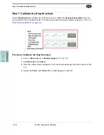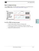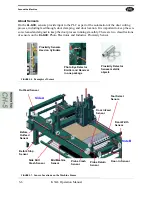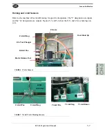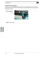
Step 6: Calibrate the Tool Holder
KVAL Operation Manual
4-17
Step 6: Calibrate the Tool Holder
Important: Proceed with Caution. Incorrect Calibration may damage the spindle or tool
holder. Input small increments when calibration.
This calibration adds offsets to align the
Cutter Head Tool Holde
r to the
Tool Holder Rack
drop off
and pick up locations. For instructions about entering calibration data,
Run the
Manual Tool Changer
Control
that is located under the
Maintenance Tab
.
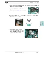
Check location of the
Cutter Head
Tool Holde
r against the
Tool
Holder Rack
then enter offsets into
the
X-Axis
,
Y-Axis
, and
Z-Axis
cali-
bration boxes to align to the
Tool
Holder.
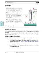
About the Manual Tool Change Mode
This calibration is best used with the
Manual Tool Change Mode.
When activated, the
Cutter Head
can be moved in repeatable steps toward, away, up, and down with reference to the
Tool Holder
Rack
. At these step intervals, the operator establishes best tool position for the
Tool Holder
and
Tool Rack.
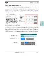
To initiate the sequence, go to the
Manual Control Tab
and locate the
Manual Tool Changer
menu.
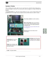
ON/ OFF and Step Control
Select Tool
Status Message Box
Summary of Contents for DL-NCD
Page 10: ...KVAL DL NCD Operation Manual Table of Contents ...
Page 28: ...How to Download the Service Application KVAL Operation Manual 1 18 ...
Page 30: ...Safety Sign Off Sheet KVAL Operation Manual 1 20 ...
Page 62: ...About the LiteCutout Feature Detail KVAL Operation Manual 2 32 ...
Page 94: ...Appendix About Backing up the Data KVAL Operation Manual 3 32 ...
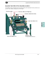
Page 118: ...Appendix Servo Motor Drive Assembly Locations KVAL Operation Manual 4 24 ...
Page 139: ...About the Electrical Panels KVAL Operation Manual 5 21 I ...
Page 142: ......
Page 143: ......


