About the DL-NCD Calibration Screen
KVAL Operation Manual
4-8
About the DL-NCD Calibration Screen
The
Calibration Screen
contains a list of calibration adjustments. Select the
DL-NCD Tab
located
on the left hand side of the machine, then select the
Calibration Tab
to jump to this menu. Enter
“How to Enter Calibration Data” on page 4-6
unlocked.
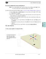
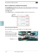
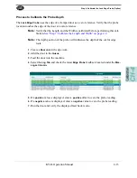
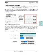
DL-NCD Calibration Screen
Calibration Selections
Calibratio
n
Assembly
Adjustments Performed
Head
Face Carriage Axes
Adjust the location of the 3 axes (X,Y,and Z) of the
Face
Carriage Head.
Edge Carriage Axes
(Option)
Adjust the location of the 3 axes (X,Y,and Z) of the
Edge
Carriage Head.
Tool Holder
Adjust the position and approach of the
Carriage Head
at the
Tool Holder Rack.
Axes X, Y, and Z.
Face Tools
Adjust the diameter of each Face tool.
Lock Edge Tool
(Option)
Adjust the Diameter and Axes X,Y,and Z of the Edge tool
Slug Knockout
Adjust the position of the Knockout in the X and Y axes.
Table
Stop 1
Adjust the Stop
Length Probe
Adjust the X-Axis if the Length Probe.
Lock Edge Probe
(Option)
Adjust the Axes X,Y,and Z of the lock Edge Probe.
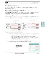
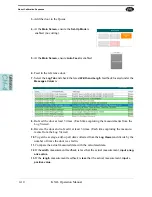
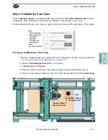
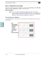
The table below describes the available calibration routine.
Summary of Contents for DL-NCD
Page 10: ...KVAL DL NCD Operation Manual Table of Contents ...
Page 28: ...How to Download the Service Application KVAL Operation Manual 1 18 ...
Page 30: ...Safety Sign Off Sheet KVAL Operation Manual 1 20 ...
Page 62: ...About the LiteCutout Feature Detail KVAL Operation Manual 2 32 ...
Page 94: ...Appendix About Backing up the Data KVAL Operation Manual 3 32 ...
Page 118: ...Appendix Servo Motor Drive Assembly Locations KVAL Operation Manual 4 24 ...
Page 139: ...About the Electrical Panels KVAL Operation Manual 5 21 I ...
Page 142: ......
Page 143: ......


