Kval DL-2 Operation And Service Manual Download Page 33

   Powering Up and Down the DL-2

2-7

KVAL DL-2 Series Operation/Service Manual

 Powering Up and Down the DL-2 

This section describes how to power up and to power down the DL-2

Powering up the system includes:

• Applying power to the entire system.

• Starting the Control Circuit.

Powering down the system includes:

• Turning off the computer.

• Shutting down the control power.

• Removing power from the entire system.

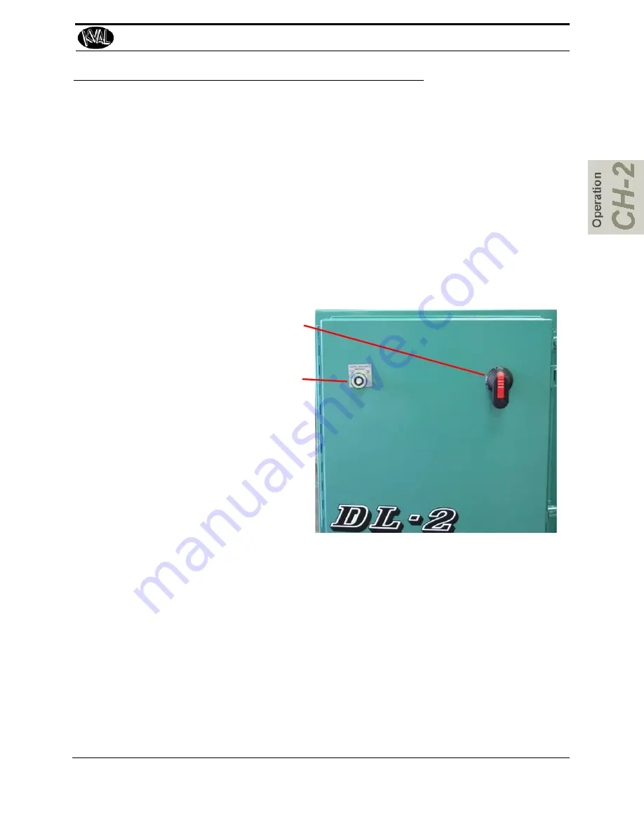
To Power Up the DL-2

1. 

 Make sure the electrical discon-

nect the electrical cabinet is 
turned to the ON position.

2. 

 Pull out the 

CONTROL TRANS-

FORMER

 switch.It should light 

up along with the Control Power 
light and the Overload Relay 
light

The DL-2 is now ready for work.

Powering Down the DL-2

1. 

 Push in the CONTROL TRANSFORMER switch.

2. 

. Kval also recommends that you turn the disconnect switch to OFF; this helps 

reduce possible damage resulting from power surges from electrical storms.

Summary of Contents for DL-2

Page 1: ...Innovation Quality Honesty Operation and Service Manual Published 7 21 16 DL 2 Door Light Cut Out Machine DL 2 Door Light Cut Out Machine ...

Page 2: ...indows 7 is a registered trademark of Microsoft Corporation All other products are trademarks or registered trademarks of their respective holders all rights reserved Reference to these products is not intended to imply affiliation with or sponsorship of Kval Incorporated Contacting KVAL Customer Service For further information about this manual or other Kval Incorpo rated products contact the Cus...

Page 3: ...ser experience with our product that is the manual the machinery the software etc What was easy or difficult to use or to learn If you could change something about the design what would it be Please email your comments and suggestions for improve ment to userexperience kvalinc com NOTE This is not a customer support email link For that please refer to the Customer Service contact information above...

Page 4: ...KVAL DL 2 Operation Service Manual ...

Page 5: ...mb 1 9 Lockout Tagout Procedure 1 10 Pre Steps Before Lockout Tagout 1 10 Lockout Tagout Power 1 10 Lockout Tagout Air Supply 1 11 Start Maintenance 1 11 Post Maintenance Steps 1 11 Zero Energy to Start Up 1 12 Getting Help from KVAL 1 14 On Line Help 1 14 Product Return Procedure 1 14 Safety Sign Off Sheet 1 17 A Note to the Operator 1 17 Chapter 2 Operation of the DL 2 Operator s Tour 2 2 Standa...

Page 6: ...ickness 2 16 About Set Collars and Templates 2 17 About Y Axis Template Bar s 2 17 About Face Bore Templates 2 18 Y Axis Template Bar Set up 2 18 Adjusting a Y Template Bar 2 19 Using Templates 2 22 Positioning the Template Index Holes 2 23 Template Drill Jig 2 24 Chapter 3 Maintenance of the DL 2 Maintenance Schedule 3 2 Maintenance NO GOES 3 4 Lubrication Schedule 3 5 Lubrication Requirements 3 ...

Page 7: ... Sensors 4 2 How Sensors Work 4 2 Troubleshooting Sensors 4 2 Important Notice about Adjusting Cylinder Speed 4 3 Adjusting Cylinder Extend Speed 4 3 Adjusting Cylinder Retraction Speed 4 3 Typical Contactor Control 4 4 About Contactor Troubleshooting 4 5 Troubleshooting Electrical Problems 4 6 If the Power Stops During Normal Operation 4 6 Troubleshooting with the Status Light Panel 4 8 ...

Page 8: ...DL 2 Door Light Machine ...

Page 9: ...ailable options page 1 2 Safety First IMPORTANT safety information is described in this section page 1 5 Lock Out Tag Out Procedure lock out and tag out the machine page 1 9 Zero Energy to Start Up Procedure to power up your machine for the first time page 1 12 Getting Help from KVAL This section describes the method to contact the KVAL service center for help The section includes how to get infor...

Page 10: ...y used A three speed Cutter Head is supported by cross mounted linear bearing shafts for length and width travel The Cutter Head can be used for metal doors and wood doors cutting down time or tool change over A Hardinge B3 1 2 ID collet is used for accurate tool holding This design eliminates cut out templates for rectangular lights since adjustable stops can be locked directly on the shaft to li...

Page 11: ...le the router with joy stick all without moving the door Option DC Dust Collection System for DL 2 C330 1 Dust Collection fan equipped with silencer cartridge filter 1 start stop switch mounted on the fan Also includes all air pipe pipe fittings clamps flexible hose and bracket bolted to the DL 2 frame to support the dust collection piping 13 foot ceiling height required for dust collection piping...

Page 12: ...ommended the sheet be signed and kept for records See Safety Sign Off Sheet on page 1 17 Option K Single Skin Enables operator to cut one skin at a time used primarily with 16 and 18 gauge doors Option N Anti Static Bar Air Blow Off Option O 8 0 Door Capability Includes door stop and accommodates maximum door length of 95 Option P Leg Extensions Four leg extensions to elevate pass line height to 3...

Page 13: ...nology of Labels In addition to the nameplate KVAL machines may have other warning labels or decals that pro vide safety information to operators Safety labels should be clearly visible to the operator and must be replaced if missing damaged or illegible There are three types of warning labels or decals DANGER means if the danger is not avoided it will cause death or serious injury WARNING means i...

Page 14: ... zero state Never clean the machine while it is running Never walk away from the machine while it is running When the Machine is ON The compressed air system connected to this machine should have a three way air valve for shut off and pressure relief All cylinders on machine are under high pressure and can be very dangerous when activated Before performing any mainte nance or repairs on this machi...

Page 15: ...irs or mainte nance lockout and tagout must be installed at all locations All maintenance and repairs to electrical circuitry should only be per formed by a qualified electrician Still has power in OFF position Electrical Prior to performing any maintenance repairs cleaning or when clearing jammed debris you must disconnect tag out or lock out the electrical and air pressure systems This should be...

Page 16: ...e is in violation of any health or safety regulation STOP pro duction It is your responsibility to immediately protect your employees against any such hazard Additional detailed safety guidelines are included in the operating instructions of this manual KVAL will be pleased to review with you any questions you may have regarding the safe operation of this machine Follow Your Company s Safety Proce...

Page 17: ... lock and tag on each disconnect Only each operator may remove their own lock and tag Important When many people are all working on the same machine you will need a multiple lockout device such as the one shown here Follow the P R O P E R lockout rule of thumb P Process shutdown R Recognize energy type electrical pneumatic mechanical etc O OFF Shut off all power sources and isolating devices P Pla...

Page 18: ...ssure spring tension weight shifts etc 2 Inform all affected personnel of the eminent shutdown and the duration of the shutdown 3 Obtain locks keys and tags from your employer s lockout center Lockout Tagout Power 4 Turn off machine See Chapter 2 for power down and power up procedures 5 Turn the disconnect switches on ALL electrical and frequency panels to the OFF position Then push the red tab to...

Page 19: ...intenance or repairs may started Post Maintenance Steps 9 After maintenance is completed the person performing the work must ensure all tools spare parts test equipment etc are completely removed and that all guards and safety devices are installed 10 Before removing the locks and tags the person who attached them shall inspect the equipment to ensure that the machine will not be put in an unsafe ...

Page 20: ...tically when energy is restored Remove Locks Each operator must remove his or her own lock and tag This will ensure that all oper ators are in a safe place when the equipment is started Perform Visual Checks If the equipment is too large to see all around it station personnel around the area and sound the personnel alarm before starting the equipment If your operation is more complex your company ...

Page 21: ...th the key to your lock Proper lockout tagout can save lives limbs and money Help make your work environment safe for you and your fellow workers Be sure to follow the P R O P E R lockout tagout procedures and that those around you do also Close the Cage Gate Verify all cage gates are securely closed Ensure all safety protocols are in effect ...

Page 22: ...hrough Thursday 6 30 AM to 1 30 PM Pacific Standard Time Friday On Line Help On machines with a Beckhoff PLC and an internet connection our service team are able to con nect run and troubleshoot your machine Ask about this procedure when calling are service team Product Return Procedure If you ve contacted Kval for help and it is determined that a return is necessary use the procedure below to ret...

Page 23: ... were modified and how With what equipment is the unit interfaced What was the application What was the system environment temperature spacing contaminants etc 3 Call Kval customer support for a Return Material Authorization RMA When you call Have the packing slip or invoice numbers available Have the documented reason for return available 4 Send the merchandise back to Kval Make sure the item s y...

Page 24: ...Getting Help from KVAL KVAL DL 2 Series Operation Service Manual 1 16 Page Intentionally Left Blank ...

Page 25: ...ys follow my company s safety procedures I have read and understand these guidelines Machine Safety Concerns I have been given a tour of the machine and understand all the safety labels E Stops and the actions to take in case of an emergency I will make sure all guards are in place before operation I will turn off the compressed air before loading hardware staples screws etc I will turn off the el...

Page 26: ...Safety Sign Off Sheet KVAL DL 2 Series Operation Service Manual 1 18 ...

Page 27: ...a door page 2 6 Powering Operations Descriptions of power up power down homing and emergency stops page 2 7 Description of Operator Controls A description of the operation of the machine Pneumatic Table Controls Edge Prep Controls Option Motor Controls Head Controls page 2 9 Setting Up for a Cut Door Stop Face Bore Templates Edge Detailing Machine Cutter Head Stops Cutter Head Door Thickness page ...

Page 28: ...op Front Side Cutting Head Stop Table Controls Back Side Cutting Head Stop Head Controls Motor Controls Cutting Head Option D Edge Prep Includes edge drill and 1 x 2 1 4 faceplate Provides a semi automatic operation enabling the machine operator to select the drill or router with a toggle valve and then activate the drill with a pushbutton or cycle the router with joy stick all without moving the ...

Page 29: ...automatic blow off consists of a bank of high pressure air nozzles to clean dust and debris as the door feeds out of the DL 2 To manually turn off the air use the slide value located on the side of the machine FIGURE 1 Air Nozzles for Blow Off of Debris High Pressure Air to Clean Door of Debris ...

Page 30: ...nts Refer the machine s electrical prints for in depth information Warning High Voltage is present in this panel at the top of the Three Phase Input even with the disconnect off If working on the panel follow disconnect protocol See Safety Sheet Sign Off Sheet on page 1 2 The Main Electrical Panel Quick Disconnect and Fuses Transformer Contactors and Thermal Over Load Circuit Relays Motors 120 Vac...

Page 31: ...E Stop 4 Stop 5 Start 6 24VDC Control Power This light illuminates when the Control Trans former turned on and the power is working on secondary side of transformer Overload Relay This circuit is jumped It should always light when the Control Power turns on E Stop The back gate is closed and Frame E stop is not activated when this light is on 24VDC This light comes on once the ACR is latch and the...

Page 32: ...resent at machine and the DL 2 main air supply valve is turned on 2 Install tooling 3 Set up the door positioning 4 Set up the cuts Set up the edge prep optional Set up the lock bore optional Set up the light cut 5 Apply power to the machine 6 Load the door 7 Make cuts Edge prep optional Lock Bore optional 8 Unload door ...

Page 33: ...n the control power Removing power from the entire system To Power Up the DL 2 1 Make sure the electrical discon nect the electrical cabinet is turned to the ON position 2 Pull out the CONTROL TRANS FORMER switch It should light up along with the Control Power light and the Overload Relay light The DL 2 is now ready for work Powering Down the DL 2 1 Push in the CONTROL TRANSFORMER switch 2 Kval al...

Page 34: ...ed on the motor carriage Momentary Stop Start Button When an Momentary Stop is activated cutting stops power is no longer supplied to the cutter motor If an Momentary Stop is activated the lights lit on the status panel will be Control Power and Overload Relay To Resume Normal Operation after a Momentary Stop If a Momentary Stop is activated Push the Start button ...

Page 35: ...s 2 9 KVAL DL 2 Series Operation Service Manual Operator Controls Pneumatic Controls Motor Controls Edge Prep Controls Head Controls Stop Set of Y Template Bars 10 included See About Y Axis Tem plate Bar s on page 2 17 ...

Page 36: ...iage Open Releases the clamps and moves the movable fence away from the fixed fence Carriage Close Brings the movable fence closer to the fixed fence Clamps Applies the door clamps Pneumatic Table with Edge Prep Controls Option The Pneumatic Controls move the Clamps and Carriage on the table and the Edge Prep Router and Drill The Edge Prep Controls operate the motors of the router and drill The Ed...

Page 37: ... Router Edge Prep Drill Pneumatic Edge Prep Controls Operator Controls 2 11 KVAL DL 2 Series Operation Service Manual Pneumatic Table Controls Carriage Open Releases the clamps and moves the movable fence away from the fixed fence Carriage Close Brings the movable fence closer to the fixed fence Clamps Applies the door clamps ...

Page 38: ...Controls Drill In Out Down This is a 3 position air switch that controls the location of the bolt drill Out the Drill Carriage pivots away from the door s edge In The Drill Carriage swing in to the door edge Down Locks the Drill into Position Drill Plunge Router IN This is a 3 position air switch that controls the plunge of the blot drill and the router After pushing the switch to the left the IN ...

Page 39: ...g head router will reciprocate up and down a distance slightly less then the length of the tools cutting edge Reciprocation should increase the life of the tool Important Leave reciprocation off when using a template There could be some chance the drill can hit the template Cutter Down Pulling the button out puts the cutter head tool in the position to cut the door Cutter Up Pushing the button in ...

Page 40: ...ce Manual 2 14 Lock Definitions Both Switches UP X axis move only Y Axis X Axis Locked Both switches DOWN Y axis move only Y Axis X Axis Locked Y DOWN X UP X and Y both unlocked Y Axis X Axis Y UP X DOWN X and Y both locked Y Axis X Axis Locked Locked ...

Page 41: ... standard DL 2 has one doorstop set to customer deadbolt specifications and a spring loaded Face Bore stop Both stops are factory set if your company provided specifications to KVAL during manufacturing 8 0 Door Stop 6 8 Door Stop Locked down with Pin Face Bore Templates The Face Bore template sometimes mounted to a clamp on the movable fence pivots out of the way when plywood templates are used T...

Page 42: ...s determines the configuration of your cut out Once you have positioned the set collars mark the shaft to identify which cut out it does Cutter Head Newer DL 2 models are equipped with mist oilers to maintain proper arbor lubrication Use AW 32 Hydraulic oil KVAL P N SYSLUBG Door Thickness The DL 2 is equipped to handle 1 3 8 and 1 thick doors If you run 2 thick doors the red hold up wheel bars and...

Page 43: ... approximate position of the dimen sions of your light cutout Tighten the set collars Make a test cut and adjust as necessary If you have templates for rectangular lights Place the template in the DL 2 With power off guide the carriage along the pattern At the four corners of the light pattern position a set collar and tighten Remove the template and make a test cut Adjust as necessary About Y Axi...

Page 44: ...art by setting up for the widest door first Once the template bar has been set up for the widest door make a test cut to ensure that all of the set collars that index the light openings are accurate adjust as necessary Install additional collars for each door width to be machined 2 from the inboard edge of the inner most door width index collar If the door widths you are machining are not of stand...

Page 45: ...nd Templates 2 19 KVAL DL 2 Series Operation Service Manual Adjusting a Y Template Bar 1 Adjust first set collar with inboard edge approx 1 1 8 from end of shaft Place bar in index assembly with collar butted against out board face of shaft holder ...

Page 46: ...ired start with the widest door width set up and work towards the narrowest You cannot set up a centered light and an off set light on the same shaft collars will interfere with each other 4 Move cutter head out to line up index pointer 1 2 bar representing cutter diameter with the dimension of your first cutting pass nearest to the fixed fence Jog the cutter head as close as possible to desired m...

Page 47: ... when setting up with tape measure 7 Set in board edge of 2nd light using steps 4 5 Note that the space between the out board edges of collars set in steps 6 7 are equal to the distance between lights 8 Set collar using steps 4 5 for the out board edge of the 2nd light 9 Setting up for only one light opening is just a matter of not installing the two center collars that create the space between li...

Page 48: ...n two different width doors If you have a template for a 32 door It can be relocated in a second set of locater holes on the machine indexing 2 nearer the outside of the door The template will then be centered over a 36 door Set Templates so the top of the template is even with the door stop and the edge of the template should be flush with the fixed side fence If you want to use the jig for more ...

Page 49: ...e door with top end of template referencing off of the door stop Use the index holes on the template index bar to accommodate different door widths Using the wrong index holes will result in an off centered light cut out Index Holes 3 0 2 10 2 8 Custom Illustration shows a standard DL 2 Stops can be located at the feed in as well ...

Page 50: ... your machine However there are times when we don t set up the jig because we didn t have your templates at time manufacture If this is the case do the following Place the template jig squared to the bottom comer closest to the operator of the template Cut off or notch the template jig at the point the top of the door intersects with the jig ...

Page 51: ...Using Templates 2 25 KVAL DL 2 Series Operation Service Manual ...

Page 52: ...ance 300 Cycles 600 Cycles 3 000 Cycles 12 000 Cycles 72 000 Cycles page 3 2 Lubrication Requirements This section describes the lubrication requirements for the machine including types of lube to use This section includes Linear Bearings Flange Bearing and Pillow Blocks Gear Motor Lubrication Requirements Ball Screws Description of Air Input System Adjusting the Air Line Lubricator Priming the Ai...

Page 53: ...erforming any maintenance repairs cleaning or when clearing jammed debris you must disconnect tagout or lockout the electrical and air pressure systems This should be done in accor dance with applicable state and or federal code requirements To view a video of the maintenance process visit the KVAL website Select the Video Tab to view videos http www kvalinc com 300 Cycles Clean Use pressured air ...

Page 54: ...with clean dry cloth 12 000 Cycles Inspect Inspect chains for proper tension or damage Inspect Inspect all air cylinders for air leaks Replace if seal is leaking Inspect Inspect hydraulic lines for loose fittings leaks and cracks Inspect Inspect ball rail shafts for pitting or abrasions Lubricate Clean and lubricate all slides and cylinder rods with dry silicone spray Lubricate Lubricate all beari...

Page 55: ...e following This machine is tuned an calibrated at the factory If any of these conditions are changed timing accuracy or damage may occur during the machine process Do not adjust air PSI above or below factory settings Do not adjust any and all flow controls from factory settings Do not remove shim stock ...

Page 56: ...of Machine Operation Dura Lith Grease KVAL P N Lube EP 2 Pillow Block Bearing Flange Block Bearing Ball Screw Every 80 Hours of Machine Operation Air Line Lubricator One drop of oil every 2 or 3 cycles Check the lines every week to two weeks Either lubricant listed below is approved to use KVAL P N SYSLUBG Chevron AW Hydraulic Oil 32 G C lubricants light AW R O Mobile DTE 24 Shell Tellus32 Gulf Ha...

Page 57: ...ation s on the machine Linear Bearings Flange Bearing and Pillow Blocks If the bearing is equipped with a grease fitting Zerk Fitting it should receive 1 Gram one pump from grease gun of Dura Lith Grease KVAL P N Lube EP 2 every 250 hours of operation Note Bearings without grease fittings have been pre lubricated at the factory and do not require further lubrication Zerk Fittings Zerk Fitting Loca...

Page 58: ...cation points Ball Nut Ball Screw End Bearing End Bearing FIGURE 3 2 Example of a Typical Ball Screw Important Make sure to clean excess grease to avoid contact with feed belts clamping areas or the door Description of Air Input The air input takes in shop air and supplies clean dry air CDA and lubricated air to the machine The clean dry air is diverted to blow off nozzles The lubricator located a...

Page 59: ...t is a good practice to check your machine lubricator to insure that it is putting the proper dose of oil in the air lines Usually 1 drop of oil every other cycle is a good rule of thumb The approved list of oil for lubricators is as fol lows KVAL P N SYSLUBG Chevron AW Hydraulic Oil 32 G C lubricants light AW R O Mobile DTE 24 Shell Tellus32 Gulf Harmony 32 To prime the lubricator find an air lin...

Page 60: ...r clockwise After you have given it about three turns no more than 1 8 at a time tap the top hex with a soft faced mallet to break loose the collet within the taper When replacing the bit insert it into the collet deep enough to ensure your cutting surface is above and below the door skin when cutting with the reciprocator turned on Once you have determined that it is in the proper distance tighte...

Page 61: ...g from the rear of the drill To Adjust Horizontally There are two adjusting screws below and to the front and rear of the main body Screwing the front one in will lower the front of the drill and screwing the back one will raise the drill Depth of Drilling There really is very little adjustment as far as the depth The only adjustment is by shimming the back of the cylinder out so the drill moves c...

Page 62: ...Adjusting Drill Unit 3 11 KVAL DL 2 Series Operation Service Manual ...

Page 63: ...nel If copies are unavailable contact the KVAL Service Department Have drawings numbers model number and serial number of machine readily available Note Chapter 4 at a Glance Section Name Summary Page Sensors Descriptions of Sensors and how they work page 4 2 About Contactor Control Describes a typical contactor control circuit page 4 4 Troubleshooting Electrical Problems Includes voltages in the ...

Page 64: ...jects without touching them An inductive proximity sensor consists of a coil and ferrite core arrangement an oscillator and detector circuit and a solid state output The ferrite core and oscillator create a field generating out the front of the sensor When a metal object enters the field a loss in amplitude occurs The detector circuit recognizes the loss of ampli tude and generates 0VDC to send to...

Page 65: ...ed and out feed problems far marks in the corners of hinge pockets and flipping screws in Hoppers However sometimes machine settling mechanics be broken in may be cause to slightly adjust extend and retraction speed If more than 1 2 turn on adjustment knobs are needed call in a specialist or check with KVAL customer service at 1 800 553 5825 Adjusting Cylinder Extend Speed Adjusting Cylinder Retra...

Page 66: ...may cause personnel injury or death Troubleshooting checks must be performed by a Qualified Electrical Technician PLC Output Fuse s Line Voltage Power Contactor Control Coil Input Power Input Power Output Control Circuit Common ON Should measure Control Voltage 120 VAC here Should measure Line Voltage here Should measure Line Voltage here Line Voltage here Should measure Relay 120 VAC DC Should me...

Page 67: ...l as a trigger to check the circuit See Troubleshooting with the Status Light Panel on page 4 8 1 Open the Main Electrical Cabinet to find the Contactor Thermal Overload Assem bly 2 Press each Green Reset button on the Thermal Overload An audible click will be heard on the tripped circuit Take note of tripped circuit 3 Once the overloads are reset verify LED s are on 4 Rerun the machine and verify...

Page 68: ... machines have signals on the computer that light up when the input or out put functions are energized respectively Computer controlled as well as non computer controlled machines have white 120V control power terminal strips This will indicate power supply from the respective circuits PLC controllers also have lights on them for the input and output functions You can easily find out which circuit...

Page 69: ...l Check for Tripped Circuits 1 Remove lock and tag outs on the main power sources 2 Manually close disconnect sensors and energize the control circuit or transformer with its respective sensor Check the Status Light Panel If all lights are observed there are no overloads or emergency stops tripped Note Most electrical problems are related to mechanical malfunction e g stuck motors jammed chain blo...

Page 70: ...Power Amber 2 Overload Relay Amber 3 E Stop Amber 4 Stop Amber 5 Start Amber 6 24VDC Green If one or more lights are OFF follow the process below to isolate the cause NOTE Be sure to proceed down the table starting with the CONTROL POWER light STEP 1 Control Power Amber If light is OFF go to item A on page 4 9 STEP 2 Overload Relay Amber If light is OFF go to item B on page 4 10 STEP 3 E Stop Ambe...

Page 71: ... VAC Terminal Strip 7 If there is no power between 1 and 2 check the secondary side of the trans former a Check between X1 and X2 If no power is measured it is a bad transformer b If there is power at X1 and X2 check the other side of the fuse If now power replace the fuse 2 Is the Disconnect Switch on the main electrical cabinet set to ON Switch 3 Is there 208 220 440 or 575 VAC to the top side i...

Page 72: ...ny E Stop buttons are pulled out NOTE Location and quantity of E Stop buttons varies depending on customer need Typical locations for E Stop buttons are near the Rear Access Gate and near the Tool Changer Access Gate Stop Light OFF Check for 120 VAC between 2 and 4 If there is voltage press the Start button If no voltage check the Stop button to make sure it is all the way out and not stuck in the...

Page 73: ...hile a second person checks for volt age between 2 and 5 If there is 120 VAC replace the ACR relay If there is no voltage while the button is held in check the wiring or the contact on the Start button Troubleshooting with the Status Light Panel 4 11 KVAL DL 2 Series Operation Service Manual ...

Page 74: ...to the 24VDC power supply Trace the output wire to the DC terminal block Disconnect all 24V positive wires from the DC from the DC terminal block except the output wire from the 24VDC power supply Check for 24VDC at between any DC and DC terminal on the DC Terminal block Reinstall the 24V positive wires one by one checking for 24VDC after installing each If at any point no voltage is found trace t...

Page 75: ...Troubleshooting with the Status Light Panel 4 13 KVAL DL 2 Series Operation Service Manual ...

Page 76: ...ls description 2 4 e stop light description 2 5 F flange block bearing maintenance schedule 3 5 G gear box maintenance schedule 3 5 H heads 2 13 I inductive proximity sensor 4 2 J joy stick operation 2 12 K KVAL getting help 1 14 L linear bearing maintenance schedule 3 5 lock defined 2 14 lockout and tagout Guidelines 1 12 lockout procedure 1 10 M main electrical panel description 2 4 Momentary St...

Page 77: ...ter contacting information 1 14 setting up 2 14 six light panel description 2 5 sequence list 2 5 start light description 4 11 start light description 2 5 status light panel description 4 8 use as troubleshooting key 4 8 stop light description 2 5 stops 2 15 cutter head 2 16 T tagout procedure 1 10 template bar setup description 2 17 drill jig 2 24 face bore 2 15 index holes 2 23 positioning 2 23 ...

Page 78: ...Notes ...

Page 79: ......

Page 80: ...partment Kval Incorporated 825 Petaluma Boulevard South Petaluma CA 94952 Contacting KVAL Phone and Fax In the U S and Canada call 800 553 5825 or fax 707 762 0485 Outside the U S and Canada call 707 762 7367 or fax 707 762 0485 Email service kvalinc com http www kvalinc com ...

Reviews: