About the Electrical Panels
KVAL 990-F4 Operation Manual
2-22
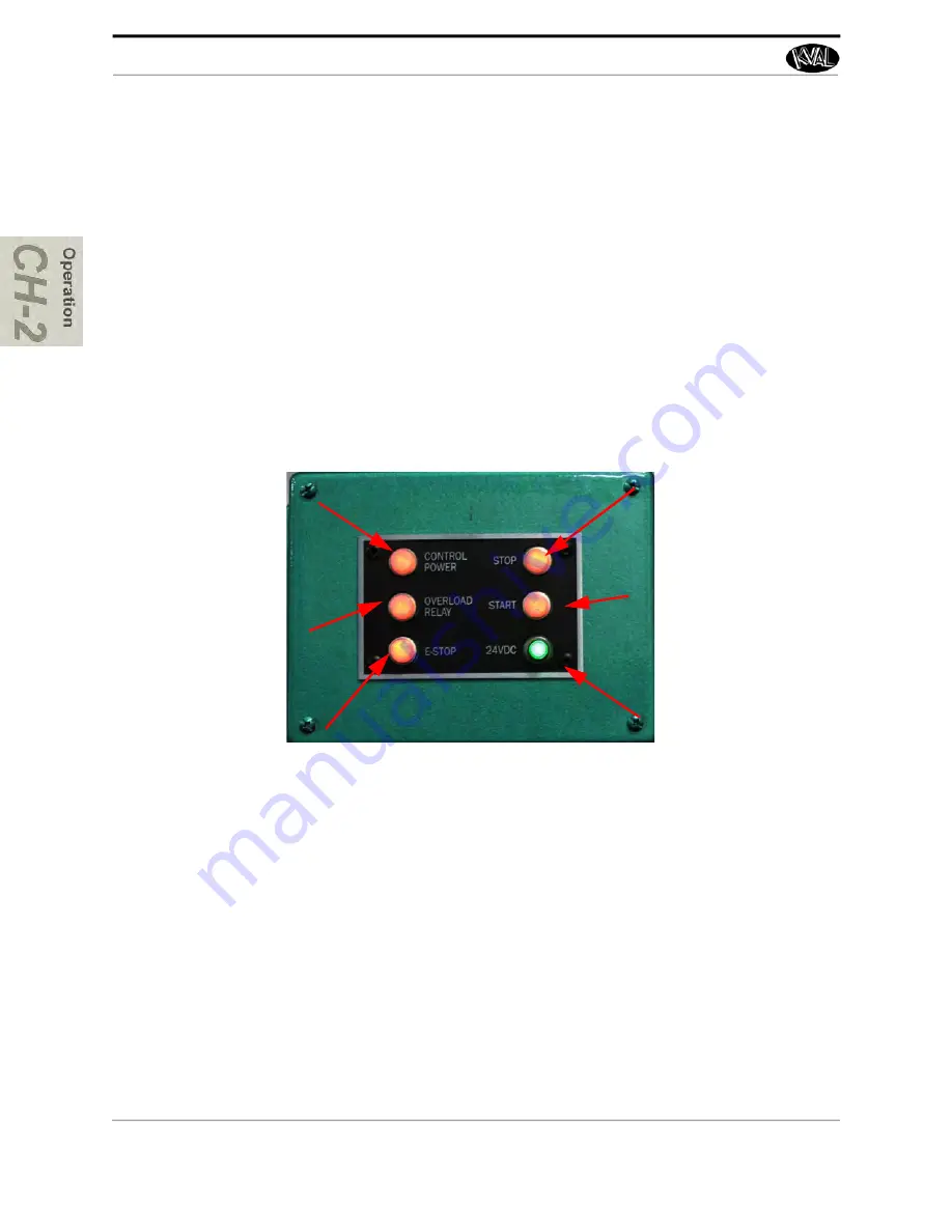
Description of the Six Light Panel
The six lights on this panel indicate the status of the m+
The Sequence that the lights activate is as follows:
1.
Control Power
2.
Overload Relay
3.
E-Stop
4.
Stop
5.
Start
6.
24VDC
About Switches and Sensors
On the
990-F4
, sensors and limit switches provide input to the PLC as part of the automation of
the door cutting process. Inputs can include feed through, door clamping, door location, and limits
of movement of machine assemblies.
Sensors are electronically tripped while limit switches are mechanically tripped. It is important to
keep the sensors cleaned and aligned to keep the door process running smoothly. There are two
classifications of sensors: Photo Electronic and Inductive Proximity Sensor.
Control Power –
light
illuminates when the
Control Transformer
is pulled out and the
power is working on
secondary side-of
transformer
Overload Relay –
The overload circuit is
working when light is
on
E-Stop –
The back
gate is closed and Frame E-stop is not acti
-
vated when this light is on.
24VDC –
light
comes on once the
ACR is latch and the
24VDC power Supply
is working
Stop –
This light will
be on if Machine
Stop button is deac
-
tivated.
Start – T
his light will
be on once the
Machine Start button
is pressed and the
ACR Relay is latched.


