background image

 Getting Help from KVAL

1-15

KVAL 990-F4 Operation Manual

Getting Help from KVAL

Before you seek help, first try the troubleshooting procedures. Follow the procedures below. 
If you are unable to resolve the problem:

1.

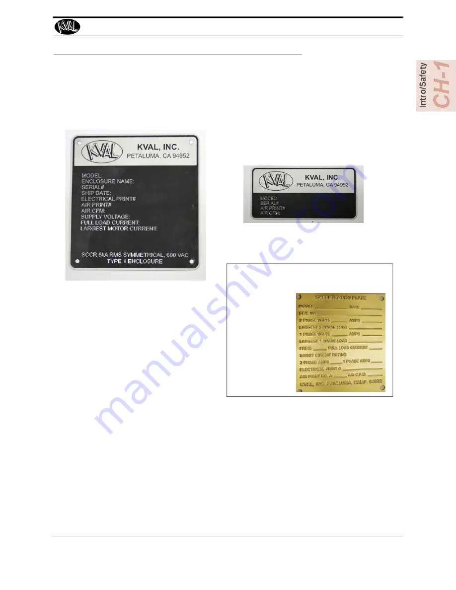
Locate the machine’s Specification Plate and record the serial number, 3 phase

volts, electrical print number, and air print number.

2.

Contact our customer support team:

• In the U.S and Canada, call (800) 553-5825 or fax (707) 762-0485
• Outside the U.S. and Canada, call (707) 762-7367 or fax (707) 762-0485
• Email address is [email protected]
• Hours:

6:00 AM to 4:00 PM Pacific Standard Time, Monday through Thursday
6:30 AM to 1:30 PM Pacific Standard Time, Friday

Air Driven Machines

Pre -2019 Machines, 

look for the brass plate.

Summary of Contents for 990-F4

Page 1: ...Innovation Quality Honesty Operation Manual Published November 12 2021 990 F4 Door Pre Hanging System 990 F4 Operation Manual ...

Page 2: ...tered trademark of Microsoft Corporation All other products are trademarks or registered trademarks of their respective holders all rights reserved Reference to these products is not intended to imply affiliation with or sponsorship of Kval Incorporated Contacting KVAL Customer Service For further information about this manual or other Kval Incorpo rated products contact the Customer Support Depar...

Page 3: ...perience with our product that is the manual the machinery the software etc What was easy or difficult to use or to learn If you could change something about the design what would it be Please email your comments and suggestions for improve ment to userexperience kvalinc com NOTE This is not a customer support email link For that please refer to the Customer Service contact information above Thank...

Page 4: ...KVAL 990 F4 Operation Manual ...

Page 5: ...Supply 1 12 Start Maintenance 1 12 Post Maintenance Steps 1 12 Zero Energy to Start Up 1 13 Getting Help from KVAL 1 15 KVAL Return and Warranty Policy 1 16 Send the Item 1 16 Acceptance of Return 1 16 Refund Turnaround Time 1 16 Kval Errors 1 16 Customer Errors 1 17 Shipper Errors 1 17 Warranty Replacement Parts 1 17 How to Download the Service Application 1 18 Download Application 1 18 Safety Si...

Page 6: ...on 2 19 About the Electrical Panels 2 21 Description of the Six Light Panel 2 22 Quick Start 2 24 Powering Operations for the 990 F4 2 26 How to Power Up the 990 F4 2 26 Home the 990 F4 2 27 How to Power Down the 990 F4 2 27 Emergency Shutdown and Recovery 2 28 Menu Map of Interface Screens 2 29 Screen Selection Menu Map 2 29 Machine Feed Back 2 31 About the Main Screen 2 32 Machine Buttons 2 33 P...

Page 7: ...out Calibration 2 40 Before you Calibrate 2 40 Flow Chart of Calibration 2 41 Using the Adjustment Menus 2 42 Enter a Positive or Negative Number 2 42 About the Entering Calibrations 2 43 Lock Location Process 2 44 Fast and Slow Lock Plate Timing 2 45 ...

Page 8: ...990 F4 Table of Contents ...

Page 9: ...an overview of the 990 F4 It includes a general description and a table of available options page 1 2 Safety First IMPORTANT safety information is described in this section page 1 1 Zero Energy to Start Up Procedure to power up your machine for the first time page 1 13 Getting Help from KVAL This section describes the method to contact the KVAL service center for help The section includes how to g...

Page 10: ...uch screen In addition custom lock bore and dead bolt locations may be entered on the touch screen for any position within the travel of the servo driven screw The servo driven system will also automatically position the lock boring assembly when the door hand is changed This machine is equipped with a solid state touch screen that replaces many of the mechanical switches for the machine functions...

Page 11: ...olt Option B Pushbutton Changeover from 3 1 2 to 4 Hinge Pockets Interior Exterior option Option BC Ball Catch Drills Drill assemblies are mounted onto the lock boring section for drilling left hand and right hand doors for drive in ball catches When selected the proper drill automatically pivots in to drill into the top of the door Note minimum door width for drilling is 18 Option C Pushbutton Se...

Page 12: ...llows hinge jamb and door to be routed at 3 degrees Eliminates the capability of 0 degrees Six Shooter or Eight Shooter is also tilted to compensate for this Requires Option D Pre Drill System for Six Shooter or Option K1 Pre Drill System for Eight Shooter Option R1 Zero Three Degree Hinge Rout ing Price includes PLC logic and controls to allow front hinge routing sec tion to rout on either a 0 de...

Page 13: ...e following Chapter Title Description 1 Introduction Descriptions of Machine Line and Safety Information 2 Operation Descriptions of how to power machine line and operator inter face user screens Chapter Title Description 1 Introduction Safety Information 2 System IT Admin istration Descriptions of the PLC system and computer system 3 Maintenance Maintenance steps for the machine line 4 Troublesho...

Page 14: ...ed or illegible There are three types of warning labels or decals DANGER means if the danger is not avoided it will cause death or serious injury WARNING means if the warning is not heeded it can cause death or serious injury CAUTION means if the precaution is not taken it may cause minor or moderate injury Safety Guidelines In addition to the caution and warning labels affixed to this machine fol...

Page 15: ...n Never perform any maintenance unless machine is at zero state Never clean the machine while it is running Never walk away from the machine while it is running When the Machine is ON The compressed air system connected to this machine should have a three way air valve for shut off and pressure relief All cylinders on machine are under high pressure and can be very dangerous when activated Before ...

Page 16: ...ted at different locations Before performing any repairs or mainte nance lockout and tagout must be installed at all locations All maintenance and repairs to electrical circuitry should only be per formed by a qualified electrician Still has power in OFF position Electrical Prior to performing any maintenance repairs cleaning or when clearing jammed debris you must disconnect tag out or lock out t...

Page 17: ...t If you believe any part or operation of this machine is in violation of any health or safety regulation STOP pro duction It is your responsibility to immediately protect your employees against any such hazard Additional detailed safety guidelines are included in the operating instructions of this manual KVAL will be pleased to review with you any questions you may have regarding the safe operati...

Page 18: ...and tag on each disconnect Only each operator may remove their own lock and tag Important When many people are all working on the same machine you will need a multiple lockout device such as the one shown here Follow the P R O P E R lockout rule of thumb P Process shutdown R Recognize energy type electrical pneumatic mechanical etc O OFF Shut off all power sources and isolating devices P Place loc...

Page 19: ... supply and pressure spring tension weight shifts etc 2 Inform all affected personnel of the eminent shutdown and the duration of the shutdown 3 Obtain locks keys and tags from your employer s lockout center 4 Turn off machine See Chapter 2 for power down and power up procedures 5 Turn the disconnect switches on ALL electrical and frequency panels to the OFF position Then push the red tab to pop i...

Page 20: ...are completely removed and that all guards and safety devices are installed 10 Before removing the locks and tags the person who attached them shall inspect the equipment to ensure that the machine will not be put in an unsafe condition when re energized 11 The lock and tag can now be removed only by the person s who placed them and the machine can be re energized 12 The tags must be destroyed and...

Page 21: ... when energy is restored Remove Locks Each operator must remove his or her own lock and tag This will ensure that all oper ators are in a safe place when the equipment is started Perform Visual Checks If the equipment is too large to see all around it station personnel around the area and sound the personnel alarm before starting the equipment If your operation is more complex your company s compr...

Page 22: ...key to your lock Proper lockout tagout can save lives limbs and money Help make your work environment safe for you and your fellow workers Be sure to follow the P R O P E R lockout tagout procedures and that those around you do also Close the Cage Gate Verify all cage gates are securely closed Ensure all safety protocols are in effect ...

Page 23: ...cord the serial number 3 phase volts electrical print number and air print number 2 Contact our customer support team In the U S and Canada call 800 553 5825 or fax 707 762 0485 Outside the U S and Canada call 707 762 7367 or fax 707 762 0485 Email address is service KVALinc com Hours 6 00 AM to 4 00 PM Pacific Standard Time Monday through Thursday 6 30 AM to 1 30 PM Pacific Standard Time Friday A...

Page 24: ... RMA _______________ Send the Item Return the item to this address Kval Inc RMA ______ Kval Parts 825 Petaluma Blvd South Petaluma CA 94952 USA Acceptance of Return We can only accept items for a return if they are still in their original packaging and in undam aged resalable condition Returns are accepted within 45 days of purchase and with an RMA number issued by Kval Inc Returns after 45 days o...

Page 25: ...o more than one 1 year after delivery will the product be covered under Warranty The repair replacement or payment in the manner described above shall be the exclusive remedy of Buyer for breach of Kval s warranty or for claims based upon failure of or defect in the products regardless of when the failure or defect arises and whether a claim however described is based upon contract warranty indemn...

Page 26: ...m 2 At the KVAL website select the Support tab Follow the instruc tions on the Support web page 3 Click the Download button to download the application that allows the KVAL technician to have access to the operator sta tion 4 After the download is com pleted double click the program icon Note Web browsers have different methods of downloading programs Below are samples of i e Explorer and Google w...

Page 27: ...rogram is ready to allow technicians to access machine computer Your Name Field Enter your name The KVAL tech nician will use this field to identify this machine Description Enter machine Serial number and issue Indicator Green indicates there is a good connec tion to the service center If red there could be an issue with a LAN connection Check the connections in the plant 7 After the KVAL Support...

Page 28: ...How to Download the Service Application KVAL 990 F4 Operation Manual 1 20 Page Intentionally Left Blank ...

Page 29: ...low my company s safety procedures I have read and understand these guidelines Machine Safety Concerns I have been given a tour of the machine and understand all the safety labels E Stops and the actions to take in case of an emergency I will make sure all guards are in place before operation I will turn off the compressed air before loading hardware staples screws etc I will turn off the electric...

Page 30: ...Safety Sign Off Sheet KVAL 990 F4 Operation Manual 1 22 ...

Page 31: ... front section parts in feed parts out feed parts back section parts the operator sta tion and the six shooter page 2 5 Quick Start A summary of the steps to machine a door page 2 24 Powering Operations for the 990 F4 Descriptions of power up power down homing and emergency stops page 2 26 Menu Map of the Interface Screens An overall description of the user interface page 2 29 Description of the U...

Page 32: ...es for the hinge screws Carriage Assembly Apply hinges Six Shooter Attach the hinges with screws Six Shooter Cut a lock and lock plate Back Section Machine Orientation The Front Section refers to the side of the machine with the operator s station and includes the three Six Shooter heads the front router motors and the pre drills The Back Section refers to side of the machine that routs the facepl...

Page 33: ...he door clamp pedal is a foot pedal that when pressed acti vates the door clamp to either clamp or unclamp the door Jamb Clamp Pedal The jamb clamp pedal is a foot pedal that when pressed activates the jamb clamps to clamp the jamb in place Routers Routers are located in on the lower front section to rout for hinges as well as a router on the back section to rout for the faceplate Six Shooters The...

Page 34: ...Line FIGURE 2 1 Typical System Setup with 990 F4 Handler Lifts and feeds door into 990 F4 990 F4 Machines door and jamb for four hinges and lock 700 C Attaches strike jamb and header to hinge jambed door from the 990 F4 PLC Controlled 558 Some Lines include a 558 Door Trim mer ...

Page 35: ... F4 FIGURE 2 2 Top View of 990 F In Feed Out Feed Front Section Operator s Station Screw Hopper Hinge Carriage 1 Six Shooter Router and Predrill Valve Bank 2 OPT BC Ball Catch Drilling Motor X2 Lock Bore Assembly Electrical Panel 1 Air Tank Valve Bank 2 Back Section Electrical Panel 2 Valve Bank 1 Hinge Carriage 2 Hinge Carriage 3 Hinge Carriage 4 ...

Page 36: ...s two Hoppers feeding to the 6 Shooter Each hopper can be filled with different colored screws Indi vidual hoppers that can be selected at the Main screen the two hoppers cut down setup time when changing screw colors To see Hopper selection see About the Main Screen on page 2 32 FIGURE 2 3 Dual Hoppers Six Shooter Assembly Identification Figure 2 2 on page 2 5 ...

Page 37: ...lling About the In Feed Section Door is input from previous machine Includes automatic or manual door width adjustment Door is feed through machine for processing The door is automatically positioned while the operator loads and clamps the door and jamb FIGURE 2 4 990 F4 In feed Operator Controls Computer interface to Run Machine In Feed System Door Enters Machine here Sensors triggered and width ...

Page 38: ...The Front Section contains Operator Station Six Shooter Machine Control Foot Pedal Hinge Carriages 1 through 4 FIGURE 2 5 990 F4 Front Section Six Shooter Machine Control Operator Station Hinge Car riage 1 Hinge Carriage 2 Hinge Carriage 3 Hinge Carriage 4 Foot Pedal Gauges ...

Page 39: ... is interlocked with a safety switch to disable the staple guns unless there is a jamb clamped in the machine Staplers Located between the 1st and 2nd and the 2nd and 3rd Carriage head For full process information see Quick Start on page 2 24 To Use this Function 1 If not already done so load the male split jamb into the female slot of the jamb 2 Load jamb assembly into machine 3 During process pr...

Page 40: ...functions such as Daily and Lifetime Totals Controls Turn ON or OFF Control Transformer Start boot up Stop turn off display and door processing E Stop Option Store Program In the off position locks out the ability to store presets and calibrate the back section In the on position unlocks the ability to store presets and calibrate the back section Displays buttons to save pre sets and displays butt...

Page 41: ... RH or a left hand LH door An optional AUTO position allows the 990 to receive hand information from previous machine Disable Auto Feed Push ing the Disable Auto Feed button will turn off the feed system Pulling the Dis able Auto Feed button out will place the 990 F4 in the feed mode selected by the FEED MODE switch Feed Mode Select Off for the manual mode Select Auto to automatically feed the doo...

Page 42: ...t Section Gauges Gauges located on the front frame display air pressure ratings of key assemblies Gauge orienta tion may vary with option of machine Below is a typical array of gauges Router Routs the hinge pocket on the jamb and the door at the same time as the counter rotate router Opt T Substitutes a 1 HP 230 380V High Fre quency Router with 1 2 collet Pre Drill Drills 6 pilot holes for inserti...

Page 43: ...t the bottom of the six shooter 3 The Six Shooter is mounted on an overhead track that is precisely aligned to ensure the hinge is properly position into the pocket at each hinge location 4 The operator a places a hinge to the magnetic indexing fixture b rolls the Six Shooter over to the hinge location and pivots it into the H block c drives all six screws into the door and jamb d presses the Rese...

Page 44: ...n Start Sequence The start sequence drops the Six Shooter into the pocket while starting motor for hydraulics It also drops the screws down aided with air injection if equipped to speed the screw feed process Hopper Slide Valve The hopper slide valve provides the operator a remote air shut off that controls air flow to the screw hopper to aid in un jamming debris in the screw drop zone Safety Inse...

Page 45: ...re being caused by the cylinders please contact the KVAL Service Department for direction FIGURE2 8 Hopper and Frame Interface Important Do not put Magnetized Screws in Hopper Magne tized screws can cause sluggish response to screws getting stuck Hopper plates could get magnetized and will have to be demagnetized with a degausser Hopper Opt Z Quick Change Dump Gate Opt Z Quick Change Dump Cylinder...

Page 46: ...d screws To start the quick change process 1 Park the Six Shooter 2 Press the Load Unload button on the Six Shooter panel The back section of the Hopper will cycle upward once to shift all the screws from the back door to clear screws between the back door of the hopper and the slides 3 Once the Hopper is in the up position the door will open and the Hopper will cycle down quickly to throw the sur...

Page 47: ...pacers X2 Factory set to align hinge Screw Receiver Tubes These tubes receive the screws from the hopper by way of plastic tubes Latch Arm Latches to H Block to secure in place Latch Arm Cylinder Moves latch arm in and out of position Hydraulic Motor Gearbox Geared to drive 6 screws simultane ously Chucks X6 Holds 6 screws aligned to the Door and the Jamb Hinge Applicator Location to attach Hinge ...

Page 48: ...e Overhead Track The Six Shooter which is supported on ball bearing equipped steel wheels and is mounted on an overhead track The track and the Six Shooter are precisely aligned to ensure the hinge is properly positioned into the pocket at each hinge location ...

Page 49: ...Drill Drills locks holes on the face of the door Bolt Drill Motor Machines lock plate on the side of the door Valve Bank Con trols Air Cylinders on back section Bolt Drill Extend and Retract Cylinder Face Plate Motor and Drill Routs face plate Ball Catch Motor and Drill Opt BC Drills ball catch on top edges for a LH or RH door X Axis Servo Motor Ball Catch Motor and Drill Opt BC Drills ball catch ...

Page 50: ...e Out Feed Section Main Machine Air Drop Opt O Air Blow off Blows off dust from the door as it Feeds Out Valve Bank Con trols frame functions Out Feed Door is fed to next stage Width is adjustable to Door X Axis Servo Motor Opt IL Hand Direction Indicator Red Light On indicates a right Hand Door is coming out to the 700 Light OFF indicates a Left Hand Door is coming out Black Button Resets 700 ...

Page 51: ...ed in Chapter 1 The Main Electrical Panel Supplies voltages to the machine Contains the PLC Programmable Logic Controller Contains a Servo Drive a DMC Digi tal Motor Control unit and an IMC Interface Motor Control The High Frequency Panel Supplies voltages to the machine Contains the PLC interface VFDs Variable Frequency Drives to interact with hinge and faceplate rout ers width adjust motors and ...

Page 52: ...d while limit switches are mechanically tripped It is important to keep the sensors cleaned and aligned to keep the door process running smoothly There are two classifications of sensors Photo Electronic and Inductive Proximity Sensor Control Power light illuminates when the Control Transformer is pulled out and the power is working on secondary side of transformer Overload Relay The overload circ...

Page 53: ...e from each other If an assembly is in between the two sensors the machine will not operate One Package The Proximity Sensor detects metallic objects without touching them An inductive proximity sensor consists of a coil and ferrite core arrangement an oscillator and detector circuit and a solid state output The ferrite core and oscillator create a field generating out the front of the sensor When...

Page 54: ...From the control bar on the middle front of the machine turn the Door switch to RH Right Hand or LH Left Hand Door Turn the Feed Mode switch to ON Auto Feed Left Hand or Right Hand Auto Feed ON Start Sequence Feed in a door from the Door Feeder Insert a Jamb pressing it firmly against the jamb stop Holding the jamb in place with hands in the proper position press the Jamb Clamp foot pedal to acti ...

Page 55: ...to the H Block using the Ryertex guides 1 Press the Start Sequence button to move the Six Shooter into position and drop the screws The six shooter will snap into place 2 When fully seated press the Insert Screw Button to attach the six screws 3 Press the Reset switch to raise the Six Shooter out of the hinge pocket and feed a set of six screws for the attachment of the next hinge 4 Repeat steps 1...

Page 56: ... gate door s are closed Note A pop up is displayed on the user screen if an E Stop is pressed The pop up will indicate which E Stop has been activated 3 Make sure the electrical disconnect the electrical cabinet is turned to the ON posi tion 4 Pull the green CONTROL TRANSFORMER switch out the ON position It should light up 5 Push the green START MACHINE button to boot up the machine Note Boot up m...

Page 57: ... shut down the operating system Note Make sure Windows is shutdown completely before turning off the machine Hard drive or data may be damaged if not turned off in this order 2 Push the green CONTROL TRANSFORMER button to the OFF position 3 KVAL also recommends that you turn the disconnect switch on the electrical cabinet to OFF this helps reduce possible damage resulting from power surges from el...

Page 58: ...pending on options of the machine the E Stop buttons may be located at various locations and of various types The E Stop switches are to be used when the machine is out of control or is about to damage personnel or equipment When an E Stop switch is activated power to the machine is killed The machine responds in the same way if you press the STOP button on the operator s station E Stop Sample ...

Page 59: ...een Diagnostic Screen and the Setup Screen Main Screen Door Parameters Preset Buttons Door Spec Width Thickness Length Hinge Spec Lock Section Manual Controls Load Hopper Shift IN Pocket Shift OUT Pocket Machine Controls Stop Door Seq Reset Machine Shut Down System Home Machine Exit Application Manual Screen Table Width Adjust Door Stop Clamp Feed Control Test Mode Lock Jog Left Right Speed Contro...

Page 60: ...top Door Seq Reset Machine Shut Down System Home Machine Exit Application Diagnostic Screen See About Calibration on page 2 40 See About the Diagnostic Screen on page 2 39 990 F4 Menus Machine Controls Stop Door Seq Reset Machine Shut Down System Home Machine Exit Application Door Count Daily Count Total Count Daily Reset Hinge Extend Time 3 5 Hinge 4 0 Hinge Lock Plate Extend Time ...

Page 61: ...he bottom left hand cor ner of all user screens is status feedback information The information generated is as follows 1 General Machine Status 2 Front Section Status 3 Back Section Status 4 Current Servo Positions Note Use this information to isolate issues if having prob lems with the machine 1 2 3 4 ...

Page 62: ...in screen the following can be done Run the machine in automatic mode Choose up to 12 different stored back section presets to process doors Get access to load and modify presets Turn ON or OFF assemblies on the machine to custom cut doors Navigate to other screens FIGURE 2 13 Main Screen ...

Page 63: ... the position is stored and then used to calculate the location of all moves after this The home sequence must be performed every time the machine is powered up or reset Reset Button If a fault occurs that cannot be cleared press the Reset Machine button This button will reset the machine to the start position before homing Press Home Machine after Reset Machine Stop Sequence Button This button st...

Page 64: ...ed or custom manual settings are being used Door Thickness Choose the desired door thickness settings Door Length Choose desired the door length settings Door Handing Displays the hand of the door Hinge Specs Set the parameters for the hinges in the Hinge Spec group The settings include Yellow Enable Disable button for Hinge Press Button to toggle both Predrill and Hinge ON or OFF Enable Disable b...

Page 65: ...Lock 1 Lock 2 and Lock 3 Lock location is displayed fore each defined lock location The settings include Yellow Enable Disable button for Lock Press button to toggle all Lock setting ON or OFF Lock Bore Press button to toggle the Lock Bore for Shallow Drill and On or OFF Bolt Drill Press button to toggle the Bolt Drill ON or OFF Face Plate Router Press button to toggle the Face Plate Router ON or ...

Page 66: ...s screen is mainly used in troubleshooting checking cut specifications and maintenance FIGURE 2 14 Manual Screen Test Mode Test Mode Select to toggle the Test Mode on or off Test Mode runs the hinge cycle but does not extend the tools This is primarily used to verify a new template is correct and the hinge carriage will not bump into the H Block or other assemblies ...

Page 67: ...lso stop if the positive travel limit eye is activated Close Press and hold the Close button to close the width adjust carriage To stop the carriage release the button The carriage will also stop if the negative travel limit eye is activated Door Stop Press the Stop button to extend or retract the door stop Clamp Press Clamp to activate the cylinders that clamp the door Feed Reverse Press and hold...

Page 68: ...ress to start the burn sequence a new hole will be slowly drilled the process will automatically stop when finished See the Service Manual for information on Chipout Replacement Hopper Functions This Section contains buttons to load the Hop per Load the 6 Shooter Hopper Press the button to start the screw loading process This action can also can be operated at the 6 Shooter assembly Hopper Screw T...

Page 69: ...t is running If the machine issue can not be resolved call KVAL Inc 1 800 553 5825 Have any error code that is displayed ready to give the KVAL representative This will aid in troubleshooting and shorten down time The Diagnostic screen keeps track of the all the doors processed on the machine The quantity is displayed in the Total Door Count box To keep track of daily production the quantity of do...

Page 70: ...damaging tooling or product The Test Function button is located under the Manual Screen Before you start calibration check for the following common issues and ask yourself these ques tions 1 Is the loaded setup correct for the current cut 2 Are the machine stops set up correctly 3 When did the problem first start during a run at start up 4 When was the last calibration 5 Is the door square straigh...

Page 71: ...bout Calibration 2 41 KVAL 990 F4 Operation Manual Flow Chart of Calibration The flow chart below illustrates the steps in performing a calibration on the 990 F4 FIGURE 2 15 Calibration Process Flowchart ...

Page 72: ...r by using your Left Hand Use the cut on the door as a reference Looking into the cut from the front of the machine Hold out the left hand with the first finger pointed at the door second finger and thumb at right angle to each other The first finger represents the positive direction of the Z axis The thumb represents the positive direction of the Y axis The Second finger represents the positive t...

Page 73: ...About Calibration 2 43 KVAL 990 F4 Operation Manual About the Entering Calibrations Press the Setup Button to jump to the Setup Menus FIGURE 2 17 Machine Calibration Screen ...

Page 74: ...the back section Adjustments can be made for right hand and left hand doors for 6 8 7 0 and 8 0 door sizes Lock Location 1 Select the size door 6 8 7 0 8 0 2 Select Right Hand or Left Hand depending on the door run through process 3 Under Base select the Combine with Base but ton 4 Point of view Front looking into the machine Enter a positive number to move the lock cut to the right Enter a negati...

Page 75: ...sure the flow controls are set properly If the settings are in Extend Time adjust the Slow Lock Plate Timing Vertical If the vertical time is not making it up or down before the horizontal move starts enter a larger number This number is in seconds If there is a delay before the hori zontal moves enter a smaller number in this box Continue entering numbers until timing is matched Horizontal If the...

Page 76: ...About Calibration KVAL 990 F4 Operation Manual 2 46 ...

Page 77: ...panels description2 21 emergency shutdown description2 28 e stop light description2 22 F feed system timing description2 45 front section key assemblies2 12 front section status feedback2 31 H high frequency panel description2 21 high voltage electrical panel2 21 home button description user interface2 33 using2 27 I inductive proximity sensor2 22 input and output terminals location electrical pan...

Page 78: ...ety guidelines1 6 Safety Sign Off Sheet Safety Concerns1 21 sensors types2 22 voltage levels2 23 servo drives location in main electrical panel2 21 servo positions feedback2 31 shut down system description user interface2 33 six light panel description2 22 sequence list2 22 start light description2 22 start machine button power up2 26 stop light description2 22 stop sequence button description use...

Page 79: ......

Page 80: ...partment Kval Incorporated 825 Petaluma Boulevard South Petaluma CA 94952 Contacting KVAL Phone and Fax In the U S and Canada call 800 553 5825 or fax 707 762 0485 Outside the U S and Canada call 707 762 7367 or fax 707 762 0485 Email service kvalinc com http www kvalinc com ...

Reviews: