background image

Summary of Contents for K2000R

Page 1: ...KURZWEIL KZCKXVKZOOOR SERVICE MANUAL KURZWEIL Kurzweil is a product line of Young Chang America Inc Young Chang America 13336 Alondra Blvd Cerritos CA 90701 2205 P N 92002000...

Page 2: ...not qualify its owner or user as a competent service technician on this product Any attempts to repair modify adjust or service any internal component or assembly by non approved personnel may void al...

Page 3: ...d with a stand or cart that is recommended by the manufacturer 6 This product either alone or in combination with an amplifier and speakers or headphones may be capable of producing sound levels that...

Page 4: ...enna Increase the separation between the instrument and the receiver Connect the instrument into an outlet on a circuit different from the If necessary consult your dealer or an experienced radio tele...

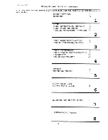
Page 5: ...1 SETUP 1 K2000 OPERATIONAL CHECKOUT 5 K2000 POWER UP CHECK 11 K2000R OPERATIONAL CHECKOUT 17 2 K2000 DISASSEMBLY ACCESS 1 K2000R DISASSEMBLY ACCESS 7 3 K2000 MAINTENANCE 1 K2000 K2000R TROUBLESHOOTI...

Page 6: ...pad 8 Megabytes of 16 bit sample ROM including acoustic instrumental sounds waveforms and noise 20 KHz maximum bandwidth Optional stereo sampler with analog and digital inputs Sound ROM expandable to...

Page 7: ...es of ROM 16 bit samples Built in 3 5 floppy drive HD DD Two SCSI buses for connection with external SCSI disks CD ROM or Macintosh computers Ten analog outputs including four stereo pairs and a stere...

Page 8: ...um 104 F 40 C For storage minimum F C maximum 186 F 85 C Relative humidity ranges non condensing Operation and storage 5 95 1 PHYSICAL SPECIFICATIONS Overall dimensions K2000 Width 40 15 16 in 104 cm...

Page 9: ...oscillations in voltage are analogous to the waveforms of the sounds they generate Compare digital In terms of sound generation the range of frequencies within which a device functions The human ear h...

Page 10: ...s and Os by converting them into an electrical signal that is always in one of two very definite states on or off this is much more precise than the analog method therefore digital computers can opera...

Page 11: ...he contents of RAM Press the Reset button in Master mode to do a hard reset This is a quick way to restore the factory defaults to the K2000 but EVERYTHING in RAM all the objects the owner artist has...

Page 12: ...ject you edit These spaces are called banks Each bank can hold up to 100 objects of each type so we refer to them as the 100s bank the 200s bank and so on The ID of an object determines in which bank...

Page 13: ...locks it depending on whether it is receiving an electrical charge The combination of light and dark dots creates a pattern which you recognize as text or graphics The K2000 s display is 240 by 64 pix...

Page 14: ...he 0 and CLEAR buttons to do a soft reset IF your K2000 is hung up for some reason this will usually get take care of the problem See Hard Reset A device which converts motion into discrete on off sig...

Page 15: ...oint in the digital representation of a sound s waveform where the digital signal is neither positive or negative When looping samples starting the loop at one of these points will reduce or eliminate...

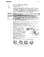
Page 16: ...IFIED SERVICE PERSONNEL 2 1 2 To change the selected voltage 1 2 3 4 5 6 7 8 Turn the unit off and remove the AC line cord from the AC power connector Open the cover of the fuse voltage select compart...

Page 17: ...an fuse NOTE When preparing the unit for use on European or other 220 240V 50HZ AC lines the fusing arrangement must be changed in order to fully protect the instrioment 2 2 3 To change from the North...

Page 18: ...the Bank A sockets When installing two banks 4 SIMMs of different sizes make certain the 2 SIMMs in the Bank A sockets are the same size and the 2 in the Bank B sockets are the same size Insert a SIMM...

Page 19: ...l Be careful not to damage the traces on the board 4 Carefully insert the new IC labeled LO in the socket at U3 and the new IC labeled HI in the socket at U6 Make certain the ICs are oriented with pin...

Page 20: ...channels and controls in each zone Press the Quick Access mode button and use the numeric keys to select from programmable banks of ten programs or setups Insert a program library disk into the floppy...

Page 21: ...ct the power cord to the K2000 first then to a properly grounded three prong power outlet If your power source does not have the standard three prong outlet you should take the time to install a prope...

Page 22: ...with effects at the MIX outputs and second the layer s sound will appear without effects at the Group A outputs if standard audio cables are inserted into the Group A output jacks Set the value of th...

Page 23: ...nly at the left or right output If you are using the K2000 for recording and multi timbral sequencing you will need to use the separate outputs to increase the mix down options and for adding outboard...

Page 24: ...r more of the K2000 s separate outputs many audio configurations with outboard gear can be created The tip of the stereo end carries the signal to the send side of the split end and the ring of the st...

Page 25: ...unconnected The output from the other instrument will appear at the K2000 s MIX outputs along with any sounds from the K2000 that are routed to the MIX outputs If the insert cable is plugged into the...

Page 26: ...THREE TIMES If the battery voltage is below 3 2 volts Note that scanner also reports a low voltage to the engine board which will display low voltage POWER ON DIAGNOSTICS Power on diagnostics are limi...

Page 27: ...Mode buttons will also blink their respective LEDs 2 16 12 KEY TESTS Press the Hi C key The LCD will display KEY C7 96 C7 96 Translation the first of two key contacts makes about one half travel and...

Page 28: ...nd 107 Space Flange A small artifact maybe present during switching or in the background of the flange effect Note that setting the offset adjustment to a null point for the pop artifact may increase...

Page 29: ...put the piano without Effects or volume fader To exit press EXIT then NO button F Returns to default settings MIDI JACK TEST Feed a MIDI signal into the MIDI IN jack This MIDI signal should appear at...

Page 30: ...ests 2 17 11 1 INDIVIDUAL TESTS Move the cursor to the desired test and press ENTER The test will run once and the LCD will display SUCCESS or ERROR DATA EXP is for expected data OBS is for observed d...

Page 31: ...RCH8CK DOC 12 22 92 Total test passes 5 minus failures 5 SCSI failures 0 5 5 0 Assuming no hard drive installed this tells you all ROM RAM passed 5 Alternate test Run individual test on each ROM RAM i...

Page 32: ...nes or run standard 1 4 inch audio cables from the MIX audio outputs to your sound system us the MIX L out for mono Connect a MIDI cable from the MIDI Out port of your MIDI controller to the MIDI In p...

Page 33: ...amage To provide adequate ventilation the rear panel should be at least four inches from any vertical surface There are no user serviceable parts in the K2000R Under no circumstances should any attemp...

Page 34: ...nal synths personal computers MIDI effects processors and MIDI patch bays Depending on your system you may want to use the K2000R s MIDI Thru port to pass MIDI information from your MIDI controller to...

Page 35: ...b 0ctau4iiPanic 1 Righteous Piano Figure 2 10 Program Mode Display Set the volxime at a comfortable level You will get the best signal to noise ratio if you keep the K2000R at full volume turn the vol...

Page 36: ...and it indicates the voltage the K2000R is set for 2 19 2 To Change the Selected Voltage Turn the unit off and remove the AC line cord from the AC power connector Locate the Voltage Selector Card whi...

Page 37: ...se Removal Lever labeled Fuse Pull and raise this lever until the adjacent fuse is free of its clip mount Remove the fuse Insert the new fuse and press completely into the clip mount Close the clear p...

Page 38: ...LL ANTI STATIC PRECAUTIONS WHEN HANDLING SIMMs Turn the unit off and remove the AC line cord from the AC power connector Open the unit as described in Section 3 of the Service Manual Locate the SIMM s...

Page 39: ...the above three steps to install remaining SIMMs Once all SIMMs have been inserted inspect for proper installation make certain the top edges of all like SIMMs are at the same height and parallel to t...

Page 40: ...lly insert the new IC labeled LO in the socket at U3 and the new IC labeled HI in the socket at U6 Make sure the ICs are oriented with pin 1 towards the front of the unit Pin 1 is on the end of the IC...

Page 41: ...ly remembered 3 1 2 Place K2000 upside down on clean smooth padded surface CARE MUST BE TAKEN TO POSITION THE UNIT SO AS TO PROTECT THE WHEELS FROM DAMAGE Using a 2 Phillips screwdriver remove the six...

Page 42: ...Using a 2 Phillips screwdriver remove twelve 12 self tapping screws securing both boards six for each board Carefully lift the assembly consisting of both boards and the metal chassis from the unit A...

Page 43: ...e four 4 self tapping screws securing the LCD and lift the board free Reverse 3 2 7 to reinstall FRONT PANEL REMOVAL Before removing the bottom half of the shell remove the round knob on the Front Pan...

Page 44: ...Power board located in the lower right hand corner of the board Locate the Wheels Interface board in the lower right hand corner of the unit and disconnect the 4 pin ribbon mylar connector this connec...

Page 45: ...he positioning of the two ends The wide end of the spring goes to the the top of the key This can be easily removed with a pair of needle nose pliers by lifting one end of the spring out of its socket...

Page 46: ...ove the two 2 hex head screws securing the connector labeled SCSI THRU J412 to the rear panel Remove the ten 10 nuts securing the 1 4 jacks to the rear panel Lift out the K2000R Connector Board Revers...

Page 47: ...om Gently remove the escutcheon 3 3 5 1 Display Removal Using a 2 Phillips screwdriver remove the four 4 screws mounting the Display to the frame Trace the twisted pair of yellow wires to J2 on the Ba...

Page 48: ...NG THE K2000 It is always a good idea to remove dust from the K2000 occasionally Dust can be easily removed by using the brush attachment with a vacuum cleaner and gently working same into the gaps be...

Page 49: ...least a year after installation while alkaline batteries should last for at least 2 years provided they are installed before the date on the package Rechargeable batteries should not be used the K200...

Page 50: ...performing a soft reset press 0 CLR together after plugging in a backward footswitch will result in proper operation 4 4 7 The diagnostic program may be used to examine the action of a control pedal...

Page 51: ...MIZING NOISE The K2000 quite possibly has the lowest noise and widest dynamic range of any instrument in the industry The following tips will enable you to make the most of this and optimize the K2000...

Page 52: ...ious effects Your best signal to noise ratio will be achieved by setting the effects level parameters to maximum and adjusting the Wet Dry Mix parameter to set the overall effects mix If you are only...

Page 53: ...to and stays at an acceptable level for at least one second the computer will automatically restart The net effect is just as if you had performed a soft reset Continuous low line voltage or transien...

Page 54: ...ure doesn t work the service technician should contact the Kurzweil Service Department Check that the Volume slider is at least partially up from it s bottom position Reaffirm that the proper audio ca...

Page 55: ...Incorrect voltage selection setting REFER TO SECTION 2 FOR DETAILS IN CHANGING SELECTION 5 Open primary fuse in AC power connector 6 Defective power switch AC power connector power transformer in K200...

Page 56: ...de for detailed configurations 1 This is normal When a cable is plugged into the left MIX output alone both the left AND the right audio signals are routed to the jack When a cable is plugged into rig...

Page 57: ...eter If this fails hold the ENTER button and turn the Alpha Wheel clockwise to make display darker counterclockwise to make it lighter Then adjust the Master mode Contrast parameter to a higher value...

Page 58: ...ose to run the standard Burn in test or you can select individual tests to diagnose specific components The Burn in test automatically initiates a series of tests to check the basic functionality of t...

Page 59: ...tests are done multiple times to make sure the unit will perform properly with extended use stib lPUerSW Rudia BbardllOpti ottBoard MIDlf Uapt SinegiWawe SbUrid ROM SbUhdsRGM 1st NURRM Figure 4 3 Diag...

Page 60: ...than once because the K2000 can only recognize switch closures between tests Press any front panel button to interrupt the Burn in test temporarily The test will resume when the button is released Pre...

Page 61: ...est data pattern is written from the processor to the memory component being tested The diagnostic software expects the data pattern that s written to memory to be read back exactly as it was written...

Page 62: ...4 13 3 I O Tests In an I O test a test data pattern is sent from the CPU to the component being tested The signal is processed by the component and returned to the central processor If the signal retu...

Page 63: ...are and locations U2 and U5 are unused Nevertheless the Boot EPROM test checks the Engine software EPROMs 4 14 3 Setup EPROM Test Similar to the Boot EPROM test this is intended to check the data and...

Page 64: ...and their connections The test entails sending a test data pattern from the floppy disk controller FDC to the floppy disk drive FDD and back If the display indicates a successful test then the connec...

Page 65: ...0 and Hobbes 1 Calvin handles sample fetching tasks and Hobbes 0 and 1 primarily perform wave form generation and DSP functions Calvin and Hobbes have undergone rigorous testing prior to mass manufac...

Page 66: ...est Fail Connection problem between CPU and Calvin 2 2 Hobbes 0 Memory Test Fail Connection problem between CPU and Hobbes 0 2 3 Hobbes 1 Memory Test Fail Connection problem between CPU and Hobbes 1 3...

Page 67: ...urity of the sine wave generated If the sine wave is impure a problem with the sound engine is suggested To monitor the Sine wave test connect the scope to any of the B outputs the MIX outputs or the...

Page 68: ...bs Rddress ExK R Saccess B Success C Success D Success Press anykey to centinue M m m i v m a m m V Obs Figure 4 8 Sound RAM Test currently checking Bank 1 Block B If any of the SIMMs is defective or...

Page 69: ...s processor which is called the Scanner then communicates its findings to the main 68301 processor CPU The scanner is on the Audio Power board at location U30 and is a single chip 6502 derived process...

Page 70: ...to 3 2 volts The wheel center should be between 120 and 136 inclusive for full range operation The fourth line represented by XXXX is generally the one of interest If it is flickering move the right w...

Page 71: ...ls especially Roland are normally closed and open only when pressed Most others are normally open and close when pressed The K2000 can use either type as long as it is plugged in before powering up bu...

Page 72: ...g under the board or current leakage in the audio power board The LCD based diagnostic may be exited and normal K2000 operation restored by pressing the EXIT and ENTER buttons together The K2000 shoul...

Page 73: ...s are 80 128 for a total of A7 167 I be 10100111 either wheel the Controller ue to appear in hex on the LE of which control changed you sically is the one the scanne edal 1 is closed the LEDs wi y wil...

Page 74: ...ft C 34 QUICK ACCESS 64 MASTER A3 EDIT A2 CHAN BANK UP A1 CHAN BANK DOWN When a key is pressed partially its MIDI note number is displayed dimly in hexadecimal The MIDI note numbers range from 24 deci...

Page 75: ...the K2000 s diagnostic mode a menu of available tests will display The options are to run the standard Burn in test or to select individual tests to diagnose specific components The Burn in test autom...

Page 76: ...he appropriate test s from the normal diagnostics menu If repairs or replacement of parts are necessary it is advised to run the Burn in test one or more times when repairs are finished 4 19 2 Running...

Page 77: ...the result of the test Normally each test need only be run once in the attempt to identify failures If you encounter test failures you may want to run the failed test continuously Running a given tes...

Page 78: ...ddress where the failure occurred the expected hex value at that address the actual observed value at that address See Figure 4 15 for an example Test xtem Please wait Ted irtgv 4iata Err gtfdress r i...

Page 79: ...ibed below will be either a memory test or an I O test in some cases a combination of the two When performing single passes of specific tests the display will indicate the result of the test upon its...

Page 80: ...he engine board The results will be either Success Data Failure or Address Failure If this test fails the RAM chips should be replaced If unit has the P RAM option the test will take approximately 45...

Page 81: ...ing this test The test cannot proceed without a disk inserted in the drive The FDC floppy disk controller test is an I O test and checks the functionality of the NEC PD72064 chip the floppy disk drive...

Page 82: ...ved values are not given on the line indicating the status of test 2 Instead a PASS or FAIL message will be indicated for each of the three steps in test 2 NOTE The Calvin and Hobbes tests are interre...

Page 83: ...m between Calvin and Hobbes 0 A Hobbes 0 Read Only Test Fail Connection problem between Calvin and Hobbes 0 B Hobbes 1 Read Only Test Fail Connection problem between Hobbes 0 and Hobbes 1 4 21 12 Samp...

Page 84: ...he unlikely event of a failure the engine board must be replaced since the Sound ROM chips are soldered in place 4 21 15 Sound RAM Test This memory test checks the address space of the sample RAM SIMM...

Page 85: ...ilure or address failure as described in the overview A failure may also indicate a faulty connection between the Sound RAM and the engine board See Figure 4 19 for an example of a failure message In...

Page 86: ...croprocessor to scan the keyboard read the orofeJ nr operate the front panel buttons and LEDs This main called the Scanner then communicates its findings to the f nnt 2 si gle chip 6502 derlved proces...

Page 87: ...is flickering move the right wheel toward the center If it shows PEDAL 1 or PEDAL 2 unplug the switch pedals Now when any button or control connected to the scanner changes the name of that component...

Page 88: ...scanner diagnostics expect to see a normally open pedal After testing a normally closed switch pedal the pedal must be unplugged to clear the fourth line of the LCD This applies to Switch Pedal 2 also...

Page 89: ...ted and normal K2000 operation restored by pressing the EXIT and ENTER buttons together The K2000 should restart just as if a soft reset had occurred 4 23 2 Using the LED Scanner diagnostics In cases...

Page 90: ......

Page 91: ...4 QUICK ACCESS 64 MASTER A3 EDIT When a key xs pressed partially its MIDI note number is displayed dimly in hexadecimal The MIDI note numbers range from 24 decimal 36 for the lowest key to 60 decimal...

Page 92: ...e K2000R is not so equipped DO NOT REMOVE ANY PANELS DO NOT USE STRONG CLEANERS OR SPRAY ANYTHING ON THE FRONT PANEL OR INTO VENTILATION HOLES 4 26 Floppy Drive Maintenance 4 26 1 Refer to paragraph 4...

Page 93: ...ls Maximizing Music and Minimizing Noise Refer to paragraph 4 5 on page 4 of this section for details Ground Hum Refer to paragraph 4 6 on page 5 of this section for details Power Problems and Solutio...

Page 94: ...cause there are 61 keys on the key board only 58 of the 64 positions on the treble circuit board are connected The matrix part of which is diagrammed below is connected such that the 8 columns are dri...

Page 95: ...contacts connections are reversed the direction of rotation will interpreted as reversed by the M37450 U60 C 5 is used to interrupt the Engine microprocessor by activating EXTIRQb at pin 6 This is acc...

Page 96: ...ot be applied until after the LCD has been initialized The LCD Vee circuit F 7 to H 7 performs these functions The pulse width modulated output from the M37450 is used as a third D A output to control...

Page 97: ...threads will cut through the wall of the shoulder washer and short circuit against the semiconductor s mounting tab flat WASHER FOH E MI comucroe JFLiT dasher FAO fH 5jA K Figure 5 1 2 1 Heatsink mou...

Page 98: ...f the custom VLSI chips on the Engine Board It is extremely important for the Engine board to know when there is sufficient voltage for proper operation so as to reset itself The mute circuit s must a...

Page 99: ...rts RESET when the 5VDCdig regulator drops out of regulation The reset circuit consists primarily of U61 H 3 It is wired as a high impedance schmidt trigger and gives a fast rise and fall time signal...

Page 100: ...chip s digital pins while the analog groundplane is under the remainder of the chip U38 U40 and surrounding components E 1 to E 4 amplify the 3 volt full scale signals from the D A converters to just...

Page 101: ...e audio path switching cases the switch is connected to the summing junction of a n inverting op amp with the input resistor at the input of the switch Signal current through the input resistor either...

Page 102: ...ERS To drive the headphones adequately a non inverting gain of 2 amplifier with a power booster stage is used Using the Left channel as an example op amp U5 1 F 6 provides the voltage gain and Q2 Q3 p...

Page 103: ...in reduces on a logarithmic scale at the rate of 005V dB The 6 5 1 voltage divider formed by R106 and R103 make this 039V dB which for a 5 volt control range translates into 128dB of control range The...

Page 104: ...of the input signal Voltages higher than 8 0 volts peak at this point will be clipped by the A D converter U50 performs A D conversion by sending trial values to U16 which converts them into analog cu...

Page 105: ...onding microcode data is received from the MCD bus The Analog I O Port consists of the DAC bus and control signals MSREG LSREG S HL and S HR Sixteen bit values destined for the D A converter are outpu...

Page 106: ...M area of 56K addresses 2000 FFFF and an other area addresses 0000 1FFF Gate U58 6 splits the other area into 7K of external RAM from 0400 1FFF and IK of I O and internal RAM between 0000 and 03FF The...

Page 107: ...ses while the former is the actual Write Enable signal to the microcode RAM Counters U21 and U23 B 1 to B 3 are also involved in sequential address generation RVB_MUTE is produced by the Effects Micro...

Page 108: ...SECTION 5 BLOCK PUB 11 09 92 M 9I BATA T9 F M CAftMe Figure 5 1 6 1 Audio Board Functional Block Diagram 15...

Page 109: ...PPLY BOARD J1 Pin No Color To From 1 brown Slider Board Jl 1 2 red tf Jl 2 3 orange ft Jl 3 4 black It Jl 4 5 black large Jl 5 6 blue tt Jl 6 7 white ft Jl 7 J2 Ribbon cable to bass end key circuit bo...

Page 110: ...Header connector to AUDIO POWER SUPPLY BOARD J7 Not used in standard configuration Ribbon cable to LCD Not used in standard configuration Ribbon cable to disk drive Pin No Color To From 1 red Disk dr...

Page 111: ...K2000 K2000R L NGlNls PCB Mcru...

Page 112: ......

Page 113: ...K2000 K2000R LNGtNE rERiniHRALS INTERFACE...

Page 114: ...u rn 4 O 5 8 4 Hhs 5 4 4 HI p o 5 8 4 p S o s 4 ii l U 4 II m 1 4 HKr frS 4 o 5 8 4 Hh5T 5 4 ks 4 4 u W vr Z o 5 8 4 u u 4 Hh 5 4 u f o 4 Hhr S 4 Hho S 4 HHo 5 S 4 l lu 8 4 H n 5 o 5 8 4 Oh g 4 Hhs 5...

Page 115: ......

Page 116: ...K2000 K2000R ENGINE...

Page 117: ...K2000 K2000R ENGINE SIMMs SAMPLE RAM...

Page 118: ......

Page 119: ......

Page 120: ...AD1864n...

Page 121: ......

Page 122: ......

Page 123: ......

Page 124: ......

Page 125: ......

Page 126: ......

Page 127: ......

Page 128: ...VR1 R1 5K PITCH CENTER 100K...

Page 129: ...K2000 SLIDER PCB VOLUME...

Page 130: ...K2000R BACKLIGHT INVERTER...

Page 131: ......

Page 132: ...K2000 K2000R PCD SCSI EXTERNAL...

Page 133: ...K2000 AUDIO POWER PCB...

Reviews: