4 | Transport, installation, storage, disposal
Connecting the machine
4.8 Connecting the machine
ü
To connect the Rework system:
a) Remove all accessories from their packages, unwrap them and lay them aside.
b) With regard to this, please also read Chapter [Technical data [
1
2
3
5
6
9
3
7
4
10
8
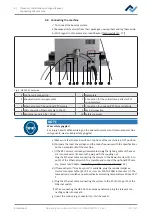
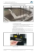
Fig. 5:
HR 550 XL back side
1 Control unit connection
6 Nameplate
2 Pneumatic system supply cable
7 Connection for the solder fume extractor PLC
control system
3 Ethernet cable of the optional RPC camera
8 Connection for optional RPC camera lighting
4 LAN connection Ethernet cable to the PC
9 Mains connection
5 Maintenance unit, 5 bar, 72 psi
10 Safety measures
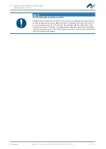
NOTE
Wear safety goggles!
Eye injury hazard! When working on the pneumatic system and pressurised machine
components, wear suitable safety goggles!
a) Make sure that the main switch on the front of the machine is in OFF position.
b) Compare the local line voltage and the mains frequency with the specifications
on the nameplate (6) of the machine.
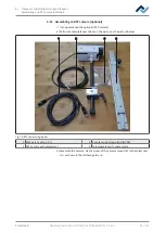
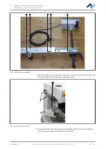
c) If the RPC camera is already preassembled, plug the lighting cable of the cam-
era into connector (8). Secure the plug with the coupling nut.
Plug the Ethernet cable connecting the camera to the Rework system (3) into
port 2 of the Ethernet switch. To assemble and connect the optional RPC cam-
era, please read Chapter Assembling an RPC camera (optional) [
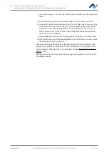
d) If fume extractor “Ersa Easy Arm” is available, plug the residual solder ex-
tractor’s modular cable (RJ-12, 2 m, item no. 3CA10-2005) into socket (7). The
fume extractor switches on automatically at working temperatures above 120°
C.
e) Plug the Ethernet cable connecting the system to the PC (4) into port 5 of the
Ethernet switch.
f) When connecting the HR 550 to a company network, plug the relevant con-
necting cable into socket 6.
g) Insert the mains plug, connector (5), into the socket.
Ersa GmbH
Operating instructions HR 550 XL EN 3BA00247-01 | Rev. 1
39 / 157

