7 | Tutorial – Soldering or unsoldering a component
Task 4 "Preparation"
7.10 Task 4 "Preparation"
If you selected the [No automation] mode:
for regular soldering. Use this method even if a component was coated with solder-
ing paste Ersa Dip & Print-Station and is ready on the Print template. The compon-
ent is picked up from the component tray, aligned and placed in the soldering posi-
tion.
a) Place the component to be soldered correctly aligned on the component tray.
Or:
a) Apply the soldering paste onto the component with the Dip & Print-Station. In-
sert the Print template with the component into the component tray holder.
Screw on the template tightly.
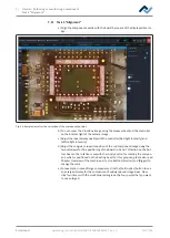
Fig. 23:
The pipette picks up the component at the laser marked point
If you selected the [Auto. Dip] dip mode, .e.g. for QFN components:
a) Place the component to be soldered correctly aligned on the component tray.
b) Spread flux gel on the Dip template with a spreading knife and insert the Dip-
template into the component tray. Screw on the template tightly.
– The wizard guides you through the work steps in order to pick up the com-
ponent and immerse it into the flux of the Dip-template. Then the com-
ponent is picked up from the DIP-template, aligned and placed in soldering
position.
Fig. 24:
Dip template on the component tray
Ersa GmbH
Operating_instructions HR 500 DE 3BA00246-01 | Rev. 1
109 / 124


