ADJUSTMENT
74
B
LEVEL MOWER DECK (Side-to-Side)
To avoid serious injury or death:
A
Park the machine on a firm and level surface.
A
Apply the parking brake.
A
Disengage PTO (OFF).
A
Stop the engine, remove the key and remove
the mower u-joint while checking or adjusting
the level of the mower deck.
A
Check the machine tire pressure.
Inflate tires to the correct pressure.
(See "TIRES AND WHEELS" section.)
C
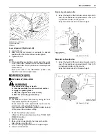
Checking level (Side-to-Side)
A
Mower deck anti-scalp rollers must not contact the
ground.
1. Raise the mower deck to the transport position. (Also
the top end).
2. Turn the cutting height set dial to the 3 in. cutting
height position.
3. Lower the mower deck.
4. Position the right mower blade in the Side-to-Side
position.
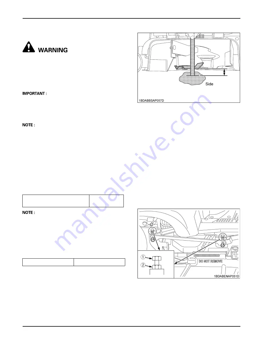
5. Measure from outside blade tip to the level surface
with a short ruler or leveling gauge.
Reference
A
There is a difference of the blade height between on
the concrete and ground.
6. Check that the left side blade is same height.
The difference between both measurements must be
less than 3 mm (0.12 in.).
7. If the Side-to-Side adjustment is not within the given
tolerance, adjustment necessary.
C
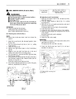
Adjusting level (Side-to-Side)
1. Raise up the mower deck to the transport position.
(Also the top end).
2. Turn the cutting height set dial to the 3 in. cutting
height position.
3. Place 51 mm (2 in.) height wood blocks under each
side of the mower deck.
Anti-scalp rollers must not rest on the wood block.
4. Lower the mower deck.
5. Position mower blade in the Side-to-Side position.
6. Loosen the lock nuts of the right side of the machine.
7. Adjust the cutting height fine tuning bolts to set 76 mm
(3 in.) height.
Front and rear side bolts must be adjusted.
8. Lock the nuts.
9. Adjust the left side equally.
10. Check the side-to-side level and if it is not level,
adjustment necessary.
Height of the blade
at the concrete surface
76 mm (3 in.)
Side-to-Side adjustment
Less than 3 mm (0.12 in.)
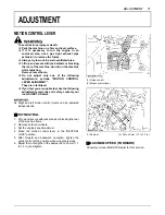
(1) Cutting height fine tuning bolt
(2) Lock nut
Summary of Contents for ZD1011-AU
Page 15: ...SAFE OPERATION 8 7 DANGER WARNING AND CAUTION LABELS ...
Page 16: ... 9 SAFE OPERATION ...
Page 17: ...SAFE OPERATION 10 ...
Page 18: ... 11 SAFE OPERATION ...
Page 21: ...SERVICING OF MACHINE 2 1 ROPS serial number ...
Page 69: ...50 MAINTENANCE PERIODIC SERVICE CHART LABEL 1 Part No K3411 6552 5 ...

