FRONT LOADER
LA525, LA765, WSM
1-S19
(2) Disassembling Control Valve
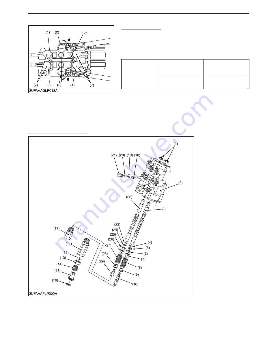
Adapter and Elbow
1. Remove the fitting, adapters and elbows from the control valve.
(When reassembling)
• Put seal tape to the fitting threads.
• Be careful not to cause damage to the O-ring.
• Install all the elbows with the angle
"A"
and
"B"
.
9Y1211014FLS0012US0
Disassembling Control Valve
Boom Control Section and Bucket Control Section
1. Remove the plug (21) and pull out the spring (19) and load check valve (18).
2. Remove the plug (11), (17) from valve body (2).
3. Remove the ring (16) and pull out the stopper (15), detent spring (14), detent ring (13), and ball (12).
4. Pull out the spool (3), (22) with other component parts from valve body (2).
9Y1211014FLS0013US0
Tightening torque
Adapter and elbow
48 to 54 N·m
4.9 to 5.5 kgf·m
35 to 40 lbf·ft
Fitting
39 to 60 N·m
4.0 to 6.1 kgf·m
29 to 44 lbf·ft
(1)
A1
Port (Adapter and Fitting)
(2)
P
Port (Elbow)
(3)
B1
Port (Adapter and Fitting)
(4)
B2
Port (Adapter and Fitting)
(5)
PB
Port (Elbow)
(6)
A2
Port (Adapter and Fitting)
(7) Dust Cap
A: 1.4 rad (80 °)
B: 1.4 rad (80 °)
(1) Dust Seal
(2) Valve Body
(3) Spool for Boom
(4) O-ring
(5) Backup Ring
(6) Collar
(7) Spring Holder 1
(8) Spring
(9) Spring Holder 2
(10) Detent Bolt 1
(11) Plug
(12) Ball
(13) Detent Ring
(14) Detent Spring
(15) Stopper
(16) Ring
(17) Plug
(18) Check Valve
(19) Spring
(20) O-ring
(21) Plug
(22) Spool for Bucket
(23) O-ring
(24) Backup Ring
(25) Collar
(26) Spring Holder 1
(27) Spring
(28) Spring Holder 2
(29) Bolt
KiSC issued 06, 2017 A
Summary of Contents for LA525
Page 1: ...LA525 LA765 WORKSHOP MANUAL FRONT LOADER KiSC issued 06 2017 A ...
Page 4: ...I INFORMATION KiSC issued 06 2017 A ...
Page 10: ...INFORMATION LA525 LA765 WSM I 5 9Y1211014INI0001US0 KiSC issued 06 2017 A ...
Page 11: ...INFORMATION LA525 LA765 WSM I 6 9Y1211014INI0002US0 KiSC issued 06 2017 A ...
Page 20: ...G GENERAL KiSC issued 06 2017 A ...


