background image

Loader model

LA344

LA344S

Capacity

Struck

0.14 m

3

 (4.9 cu.ft.)

0.13 m

3

 (4.6 cu.ft.)

Heaped

0.17 m

3

 (6.0 cu.ft.)

0.17 m

3

 (6.0 cu.ft.)

Weight

60 kg (132 lbs)

56 kg (123 lbs)


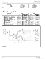
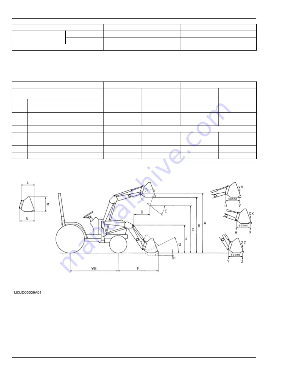
3. Dimensional specifications

Loader model

LA344

LA344S

Tractor model

BX1880

BX2380, BX2680,

and BX23S

BX1880

BX2380, BX2680,

and BX23S

A

Maximum lift height (to bucket pivot pin)

1795 mm (70.7 in.)

1804 mm (71.0 in.)

1795 mm (70.7 in.)

1804 mm (71.0 in.)

B

Maximum. lift height under level bucket

1652 mm (65.0 in.)

1662 mm (65.4 in.)

1654 mm (65.1 in.)

1664 mm (65.5 in.)

C

Clearance with bucket dumped

1316 mm (51.8 in.)

1323 mm (52.1 in.)

1281 mm (50.4 in.)

1288 mm (50.7 in.)

D

Reach at max. lift height (dumping reach)

642 mm (25.3 in.)

646 mm (25.4 in.)

673 mm (26.5 in.)

677 mm (26.5 in.)

E

Maximum dump angle

0.79 rad (45°)

F

Reach with bucket on ground

1398 mm (55.0 in.)

1392 mm (54.8 in.)

1445 mm (56.9 in.)

1438 mm (56.6 in.)

G

Bucket roll-back angle

0.52 rad (30°)

0.51 rad (29°)

0.52 rad (30°)

0.51 rad (29°)

H

Digging depth

134 mm (5.3 in.)

125 mm (4.9 in.)

132 mm (38.6 in.)

122 mm (4.8 in.)

J

Overall height in carrying position

981 mm (38.6 in.)

990 mm (39.0 in.)

981 mm (38.6 in.)

990 mm (39.0 in.)

1. INFORMATION

SPECIFICATIONS

3.Dimensional specifications

1-12

LA344, LA344S

KiSC issued 02, 2017 A

Summary of Contents for LA344

Page 1: ...LA344 LA344S WORKSHOP MANUAL FRONT LOADER KiSC issued 02 2017 A ...

Page 2: ...contains information on the structure and the function of the unit Before you continue with the subsequent sections make sure that you read this section SERVICING This section primarily contains information below Troubleshooting Servicing Specifications Tightening Torques Checking Disassembling and Servicing All illustrations photographs and specifications contained in this manual are of the newes...

Page 3: ...ts 2 7 2 Stud bolts 2 7 3 American standard screws bolts and nuts with UNC or UNF threads 2 8 4 Plugs and grease fittings 2 8 5 Hydraulic fittings 2 9 5 1 Adapters elbows and others 2 9 MAINTENANCE CHECK LIST 2 11 1 Loader service intervals 2 11 CHECK AND MAINTENANCE 2 13 1 Lubricating loader 2 13 2 Re tightening main frame bolt and nut 2 13 3 Daily checking the loader 2 13 4 Check points of every...

Page 4: ...hydraulic valve main switch 3 18 3 2 3 Checking relay 3 18 3 3 3rd function solenoid valve 3 19 3 3 1 Checking 3rd function solenoid valve continuity 3 19 3 3 2 Checking connector voltage of 3rd function solenoid valve 3 19 4 Disassembling and assembling 3 19 4 1 Removing and attaching front loader 3 19 4 1 1 Removing loader 3 19 4 1 2 Reinstalling loader 3 22 4 2 Bucket boom and hydraulic cylinde...

Page 5: ...1 INFORMATION KiSC issued 02 2017 A ...

Page 6: ...at equipment or property damage could result if instructions are not followed NOTE Gives helpful information 1 Before you start service Read all instructions and safety instructions in this manual and on your machine safety decals Clean the work area and machine Park the machine on a stable and level ground and set the parking brake Lower the implement to the ground Stop the engine then remove the...

Page 7: ...uel lines Tighten all connections before you apply the pressure Do not open a fuel system under high pressure The fluid under high pressure that stays in fuel lines can cause serious injury Do not disconnect or repair the fuel lines sensors or any other components between the fuel pump and injectors on engines with a common rail fuel system under high pressure Put on an applicable ear protective d...

Page 8: ...nt electrolyte and other dangerous waste 7 Prevent acid burns Keep electrolyte away from your eyes hands and clothing Sulfuric acid in battery electrolyte is poisonous and it can burn your skin and clothing and cause blindness If you spill electrolyte on yourself clean yourself with water and get medical aid immediately 8 Prepare for emergencies Keep a first aid kit and fire extinguisher ready at ...

Page 9: ...1 INFORMATION SAFETY FIRST 1 4 LA344 LA344S KiSC issued 02 2017 A ...

Page 10: ... pictorial safety labels are installed on the machine If a decal becomes damaged illegible or is not on the machine replace it The decal part number is listed in the parts list SAFETY DECALS 1 Safety decals 1 INFORMATION LA344 LA344S 1 5 KiSC issued 02 2017 A ...

Page 11: ...1 INFORMATION SAFETY DECALS 1 6 LA344 LA344S KiSC issued 02 2017 A ...

Page 12: ...SAFETY DECALS 1 INFORMATION LA344 LA344S 1 7 KiSC issued 02 2017 A ...

Page 13: ...bels with new labels from your local Kubota dealer If a component with danger warning and caution label s affixed is replaced with a new part make sure the new label s is are attached to the same location s as the replaced component Mount new danger warning and caution labels by applying on a clean dry surface and pressing any bubbles to the outside edge 1 INFORMATION SAFETY DECALS 2 Care of dange...

Page 14: ...raulic control lever 3 Mounting hook 4 Main frame 5 Boom cylinder 6 Boom 7 Bucket cylinder 8 Bucket 9 Lock lever 10 Mounting lever 11 Stand lever 12 Stand rod 13 Stand TERMINOLOGY 1 Loader terminology 1 INFORMATION LA344 LA344S 1 9 KiSC issued 02 2017 A ...

Page 15: ...1 INFORMATION TERMINOLOGY 1 10 LA344 LA344S KiSC issued 02 2017 A ...

Page 16: ... mm 7 7 in Control valve One detent float position single bucket dump power beyond circuit Rated flow 14 L m 3 7 GPM Maximum pressure 12 8 MPa 130 kg cm2 1850 psi Net weight approximate 217 kg 478 lbs Include the quick bucket 48 in 2 Specifications for bucket Loader model LA344 LA344S Model Square 48 in Type Rigid Quick attach Width 1219 mm 48 0 in Depth L 491 mm 19 3 in 470 mm 18 5 in Height M 46...

Page 17: ...n 1664 mm 65 5 in C Clearance with bucket dumped 1316 mm 51 8 in 1323 mm 52 1 in 1281 mm 50 4 in 1288 mm 50 7 in D Reach at max lift height dumping reach 642 mm 25 3 in 646 mm 25 4 in 673 mm 26 5 in 677 mm 26 5 in E Maximum dump angle 0 79 rad 45 F Reach with bucket on ground 1398 mm 55 0 in 1392 mm 54 8 in 1445 mm 56 9 in 1438 mm 56 6 in G Bucket roll back angle 0 52 rad 30 0 51 rad 29 0 52 rad 3...

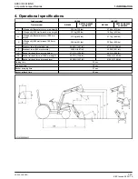
Page 18: ...00 mm height 268 kg 591 lbs 229 kg 505 lbs Y Breakout force Bucket pivot pin 6258 N 1407 lbf 5719 N 1286 lbf Z Breakout force 500 mm forward 4389 N 987 lbf 4008 N 901 lbf VV Bucket roll back force at max height 4731 N 1064 lbf 4431 N 996 lbf XX Bucket roll back force at 1500 mm height 5557 N 1249 lbf 5264 N 1183 lbf ZZ Bucket roll back force at ground level 5456 N 1227 lbf 5195 N 1168 lbf Raising ...

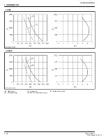
Page 19: ...LA344 LA344S A Height mm B Lift capacity kg C At pivot pin D 500 mm forward of pivot pin E Rollback force kN 1 INFORMATION SPECIFICATIONS 1 14 LA344 LA344S KiSC issued 02 2017 A ...

Page 20: ...2 GENERAL KiSC issued 02 2017 A ...

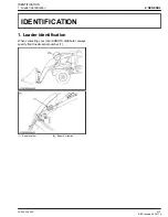
Page 21: ...identification When contacting your local KUBOTA distributor always specify front loader serial number 1 1 Serial number A Boom RH inside IDENTIFICATION 1 Loader identification 2 GENERAL LA344 LA344S 2 1 KiSC issued 02 2017 A ...

Page 22: ...2 GENERAL IDENTIFICATION 2 2 LA344 LA344S KiSC issued 02 2017 A ...

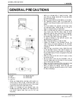
Page 23: ...harp edge 3 faces against the direction from which force 2 is applied When inserting spring pins their splits must face the direction from which a force is applied To prevent damage to the hydraulic system use specified fluid or equivalent Clean the parts before you measure them Tighten the fittings to the specified torque Too much torque can cause damage to the hydraulic units or the fittings Not...

Page 24: ...2 GENERAL 2 4 LA344 LA344S KiSC issued 02 2017 A ...

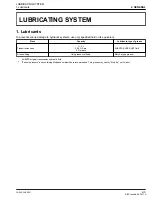
Page 25: ...nsmission case 11 3 L 2 99 U S qts 2 5 Imp qts KUBOTA SUPER UDT fluid Grease fitting Until grease overflows Moly Ep type grease KUBOTA original transmission hydraulic fluid Extreme pressure and containing Molybdenum disulfide is recommended This grease may specify Moly Ep on it s label LUBRICATING SYSTEM 1 Lubricants 2 GENERAL LA344 LA344S 2 5 KiSC issued 02 2017 A ...

Page 26: ...2 GENERAL LUBRICATING SYSTEM 2 6 LA344 LA344S KiSC issued 02 2017 A ...

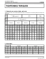
Page 27: ...29 to 32 61 to 70 6 2 to 7 2 45 to 52 M12 63 to 72 6 4 to 7 4 47 to 53 78 to 90 7 9 to 9 2 58 to 66 63 to 72 6 4 to 7 4 47 to 53 103 to 117 10 5 to 12 0 76 0 to 86 7 M14 108 to 125 11 0 to 12 8 79 6 to 92 5 124 to 147 12 6 to 15 0 91 2 to 108 167 to 196 17 0 to 20 0 123 to 144 M16 167 to 191 17 0 to 19 5 123 to 141 197 to 225 20 0 to 23 0 145 to 166 260 to 304 26 5 to 31 0 192 to 224 M18 246 to 28...

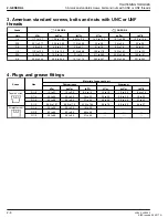
Page 28: ...44 20 8 to 24 8 151 to 179 299 to 357 30 5 to 36 4 221 to 263 4 Plugs and grease fittings Shape Size Material of opponent part Ordinariness Aluminum N m kgf m lbf ft N m kgf m lbf ft Tapered screw R1 8 13 to 21 1 3 to 2 2 9 4 to 15 13 to 19 1 3 to 2 0 9 4 to 14 R1 4 25 to 44 2 5 to 4 5 18 to 32 25 to 34 2 5 to 3 5 18 to 25 R3 8 49 to 88 5 0 to 9 0 37 to 65 49 to 58 5 0 to 6 0 37 to 43 R1 2 58 9 to...

Page 29: ...7 8 43 to 50 N m 4 4 to 5 0 kgf m 32 to 36 lbf ft Adapter NPT 1 4 30 to 50 N m 3 1 to 5 0 kgf m 23 to 36 lbf ft 3 8 39 to 60 N m 4 0 to 6 1 kgf m 29 to 44 lbf ft 1 2 49 to 58 N m 5 0 to 5 9 kgf m 37 to 42 lbf ft Grease fitting 1 8 27 4 1 to 6 7 N m 0 42 to 0 69 kgf m 3 0 to 5 0 lbf ft 1 4 18 4 1 to 6 7 N m 0 42 to 0 69 kgf m 3 0 to 5 0 lbf ft NOTE When connecting a hose with flare nut after tighte...

Page 30: ...2 GENERAL TIGHTENING TORQUES 5 Hydraulic fittings 2 10 LA344 LA344S KiSC issued 02 2017 A ...

Page 31: ...dic inspection and maintenance Check the following points before use Service intervals Check points Reference page Daily Each use Check hydraulic hoses 2 13 Every 10 hours Apply all grease fittings 2 13 Every 50 hours Check the main frame mounting bolts 2 14 MAINTENANCE CHECK LIST 1 Loader service intervals 2 GENERAL LA344 LA344S 2 11 KiSC issued 02 2017 A ...

Page 32: ...2 GENERAL MAINTENANCE CHECK LIST 2 12 LA344 LA344S KiSC issued 02 2017 A ...

Page 33: ... slightly Make sure that you can rotate the mounting pins easily and then tighten all bolts and nuts After 20 to 30 hours of initial loader operation re tighten all mounting bolts and nuts to the required torque value as follows Tightening torque table Location Bolt or nut Required torque Main frame M14 bolts or nuts 147 N m 15 0 kgf m 108 lbf ft 3 Daily checking the loader WARNING To avoid person...

Page 34: ...see a doctor at once Serious infection or allergic reaction will develop if proper medical treatment is not administered immediately 1 Cardboard 2 Hydraulic line 3 Magnifying glass 4 Check points of every 50 hours 4 1 Precautions for checking torque of bolt and nut of main frame WARNING To avoid personal injury or death Never operate the front loader with a loose main frame Any time bolts and nuts...

Page 35: ... mm 0 4 in G 58 5 mm 2 30 in H 14 mm 0 55 in I 35 0 mm 1 38 in J 0 122 rad 7 K 40 2 mm dia 1 583 in dia L 48 9 mm dia 1 925 in dia Bucket cylinder 65 mm 2 56 in A 80 B 0 157 rad 9 0 C 65 18 mm dia 2 566 in dia D 66 18 mm dia 2 606 in dia E 42 0 mm 1 65 in F 10 0 mm 0 4 in G 58 5 mm 2 30 in H 14 mm 0 55 in I 35 0 mm 1 38 in J 0 122 rad 7 K 65 2 mm dia 2 567 in dia L 73 9 mm dia 2 909 in dia SPECIAL...

Page 36: ...2 GENERAL SPECIAL TOOLS 1 Special tools for loader 2 16 LA344 LA344S KiSC issued 02 2017 A ...

Page 37: ...3 FRONT LOADER KiSC issued 02 2017 A ...

Page 38: ...of this tractor and front loader has a hydraulic pump control valve for front loader 3 point hitch system and other components This system has the following functions 1 Oil is supplied by hydraulic pump which is operated by pump drive shaft in the transmission case As the pump drive shaft is connected to the propeller shaft hydraulic pump starts operating when engine starts 2 The hydraulic pump su...

Page 39: ... min 4 12 3 to 12 7 MPa 125 to 130 kgf cm2 1780 to 1840 psi 6 0 5 MPa 5 kgf cm2 150 to 180 psi 9 9 5 L min 2 5 U S gals min 2 1 Imp gals min to the power steering controller and excessive flow to the front loader 3 FRONT LOADER MECHANISM 3 2 LA344 LA344S KiSC issued 02 2017 A ...

Page 40: ...and return through port 2 as long as operating the lever to left side with pressing the activation switch When operating lever to right side with pressing the activation switch hydraulic oil will come out of port 2 and return through port 1 as long as operating lever to right side with pressing the activation switch 3 Turn the front hydraulic valve main switch off a Push the front hydraulic valve ...

Page 41: ...er in which the reciprocating motion of the piston is controlled by hydraulic force applied to both of its ends 1 Nut 2 Piston 3 Cylinder tube 4 Head 5 Piston rod Cylinder specifications LA344 LA344S Boom cylinder Cylinder I D 40 mm 1 57 in Rod O D 25 mm 0 98 in Stroke 326 mm 12 8 in Bucket cylinder Cylinder I D 65 mm 2 56 in Rod O D 30 mm 1 18 in Stroke 196 mm 7 72 in 3 FRONT LOADER MECHANISM 3 B...

Page 42: ...onsists of the quick coupler base 5 with four hydraulic pipes 6 It is installed to the loader main frame 1 Non spill structure is adopted in the couplers on the quick coupler base to protect the oil leakage from the hydraulic oil line 1 Loader main frame 2 Quick coupler lever 3 Hydraulic hoses 4 Mobile quick coupler 5 Quick coupler base 6 Hydraulic pipe 6 Auto lock attachment and detachment 6 1 Ou...

Page 43: ... frame 5 is locked to the main frame 1 Locked position 1 Main frame 2 Hook 3 Mounting lever 4 Lever guide 5 Side frame 7 Mechanical loader frame standing mechanism 7 1 Structure of mechanical loader frame standing mechanism The loader stand 1 is fixed to the loader arm 2 by the stand hooks 5 These stand hooks 5 can be controlled by moving the stand lever 3 The stand rod 4 is connecting the stand l...

Page 44: ...ion valve If equipped 8 1 Structure of 3rd function valve P1 P1 port P2 P2 port A A port B B port C C port D D port MECHANISM 8 3rd function valve If equipped 3 FRONT LOADER LA344 LA344S 3 7 KiSC issued 02 2017 A ...

Page 45: ...r 3 Return oil from the bucket cylinder enters C port and travels throughout the valve to go to the transmission case through P2 port NOTE When the loader control lever is set to the roll back position the hydraulic oil enters from P2 port and exits at C port This extends the bucket cylinder Return oil from the bucket cylinder enters B port and travels throughout the valve to go to the transmissio...

Page 46: ...from the 3rd function cylinder enters D port and travels throughout the valve to go to the transmission case through P2 port NOTE When the loader control lever is set to the roll back position the hydraulic oil enters from P2 port and exits at D port This extends the 3rd function cylinder Return oil from the 3rd function cylinder enters A port and travels throughout the valve to go to the transmis...

Page 47: ...3 FRONT LOADER MECHANISM 8 3rd function valve If equipped 3 10 LA344 LA344S KiSC issued 02 2017 A ...

Page 48: ...lve is damaged Repair or replace control valve Tractor WSM 2 Control lever linkage is dam aged Repair or replace control lever linkage Tractor WSM Boom speed is insufficient 1 Boom cylinder tube is worn or damaged Replace boom cylinder tube 3 28 2 Boom cylinder piston ring pis ton seal and O ring is worn or damaged Replace boom cylinder piston ring piston seal and O ring 3 30 3 Oil leaks from tube...

Page 49: ...y Clean relief valve Tractor WSM 5 Oil leaks from tube joints Repair tube joints 3 28 6 Transmission fluid is insuffi cient Fill transmission fluid Tractor WSM Front end loader falls by its weight 1 Boom cylinder tube is worn or damaged Replace boom cylinder tube 3 29 2 Boom cylinder piston ring pis ton seal and O ring is worn or damaged Replace boom cylinder piston ring piston seal and O ring 3 3...

Page 50: ...ft Boom cylinder piston mounting nut 150 to 180 15 3 to 18 3 111 to 132 Bucket cylinder piston mounting nut 350 to 400 35 7 to 40 7 259 to 295 Main frame mounting bolt M14 115 11 7 85 RELATED PAGE 1 General use screws bolts and nuts on page 2 7 SERVICING 2 Tightening torques for front loader 3 FRONT LOADER LA344 LA344S 3 13 KiSC issued 02 2017 A ...

Page 51: ... adjusting blocks as shown in the following figure 1 Adjusting block 2 Adjusting bolt 3 Lock nut IMPORTANT Be sure to apply the bolts all the way to prevent the damage of the stand NOTE There is no need to tighten up the lock nuts 6 Move the hydraulic control lever to the dump position and check to see if the stands are folded as specified 7 Fasten the seat belt and start the engine 8 Move the hyd...

Page 52: ...ft side of the loader 13 Position the stand lever as shown in the figure 1 Stand lever 2 Lever guide A Center 14 Turn the adjusting bolt on the right side of the loader to set the stand pin as shown as follows 1 Adjusting bolt 2 Stand 3 Stand hook 4 Stand pin A Almost the same B Adjusting range Adjusting range B 15 mm IMPORTANT Be careful not to allow the stands to go beyond their adjustable range...

Page 53: ...d A Touch B Not touch IMPORTANT Double check that the heads of the adjusting bolts are pressed upon the stands Otherwise the stands may get damaged in storing them away 18 Be sure that the stands run parallel with the loader pipe 1 Stand 2 Loader pipe A Parallel 19 Slide the stand lever in the upward direction and make sure that the stand gets locked 1 Stand lever 2 Stand 3 Stand hook 3 FRONT LOAD...

Page 54: ...ine speed 1800 rpm 28 Slowly dump the bucket until the stand touches the boom 29 Slide the stand lever upward direction and then slide the stand lever left side completely as shown in the following figure 1 Stand lever 30 Hold the stand by stand hook 1 Stand 2 Stand hook 3 2 Front hydraulic valve main switch and relay 3 2 1 Checking front hydraulic valve main switch continuity 1 Disconnect the fro...

Page 55: ...aulic valve main switch 2 Turn the main switch on 3 Measure the voltage between terminal RB and terminal B Wire harness side B Black color of wiring RB Red Black color of wiring 4 If the measurement differs from the battery voltage wire harness is damaged 3 2 3 Checking relay 1 Remove the relay 2 Apply battery voltage across terminals 3 and 4 and check for continuity across terminals 1 and 2 A Con...

Page 56: ... on and push the front hydraulic valve main switch ON position then push the activation switch 3 Measure the voltage between terminal 1 and terminal 2 Wire harness side 1 Terminal 1 2 Terminal 2 4 If the measurement differs from the battery voltage wire harness is damaged 4 Disassembling and assembling 4 1 Removing and attaching front loader IMPORTANT To remove the loader park the tractor on flat ...

Page 57: ...ng the engine or using the hydraulic control lever always sit in the operator s seat Make sure that the bucket and the stand are at ground level 1 Set the engine speed to the following speed and then raise the boom until the bucket pin is the height of the boom fulcrum pin Engine speed 1800 rpm 2 Dump the bucket fully 1 Bucket pin 2 Boom fulcrum pin A Same height 3 Slide the stand lever downward d...

Page 58: ...he following figure 1 Hydraulic control lever 8 Down the mounting levers of both sides as shown in the following figure 1 Mounting lever 9 Back the tractor so that the quick coupler is positioned at the back of side frame as shown in the following figure 1 Quick coupler 2 Side frame 10 Stop the engine and slowly release all hydraulic pressure by moving the hydraulic control lever in all directions...

Page 59: ...rt on the coupler stay 1 Put the mobile part on the coupler stay 2 for cab model 1 Coupler stay 2 Coupler stay for cab model 15 Place the protective caps and plugs on the ends of the quick coupler 1 Protective caps 16 Wear the seat belt and slowly back the tractor away from the loader 4 1 2 Reinstalling loader CAUTION To avoid personal injury 3 FRONT LOADER SERVICING 4 Disassembling and assembling...

Page 60: ... the main frames as shown in the following figures 1 Side frame 2 Main frame A LH B RH A 150 mm to 200 mm B Center of side frames 2 Stop the engine and unfasten the seat belt 3 Remove the protective caps 4 Connect the quick coupler and lower the lever until it stops and then turn the safety lock button clockwise 1 Lever 2 Safety lock button A Lower B Clockwise IMPORTANT Get the quick coupler locke...

Page 61: ...nd run at the following speed Engine speed 1800 rpm 8 Slowly move the hydraulic control lever to the up position until the guide bosses of both side frames touch the main frames 1 Guide boss of side frame 2 Main frame A Touch 9 Slowly move the hydraulic control lever to the dump position to lower the side frames into the main frames and engage the bosses of the main frames to the guide bosses of t...

Page 62: ...e following figure 1 Mount hook IMPORTANT Make sure that the hooks at both sides are properly mounted on the main frame 1 Wire harness 2 Side frame Make sure not to pinch the wire harness in the side frame when mounting the third function kit 12 Slowly move the hydraulic control lever to the up position until the cutting edge of the bucket comes up slightly off the ground 13 Make sure that the rig...

Page 63: ... the improper positioning of handle s or non protrusion of pin s may result in detachment of the attachment or deformation causing loss of performance personal injury or death NOTE Locate the attachments on a flat firm surface when attaching and removing them from the quick attach coupler The quick attach coupler is designed to be used with KUBOTA attachments To use non KUBOTA attachments it must ...

Page 64: ...h coupler handles to the fully latched position 1 Quick attach coupler handle 7 Verify that both latching pins are completely engaged in the base of the attachment DANGER To avoid personal injury or death The following engagement points are critical The lock pins of the quick attach coupler have to protrude into and through the pin slots of the attachment on both sides It is critical that the lock...

Page 65: ...sitting in the operator s seat of the tractor start the engine and slowly move the loader control lever to the dump position until the attachment is pushed away slightly from the quick attach coupler 5 Lower the boom of the loader so that the quick attach coupler mounting plate clears the attachment saddle 6 Back away from the attachment slowly 7 If an attachment is not going to be attached to the...

Page 66: ...ble gland nut wrench 4 3 Pull out the piston rod assembly 2 from the cylinder tube 3 1 Cylinder head 2 Piston rod assembly 3 Cylinder tube 4 Adjustable gland nut wrench When reassembling Visually inspect the cylinder tube for signs of scoring or damage Put the piston rod assembly to the cylinder tube Be careful not to cause damage to the piston seal on the piston Install the cylinder head to the c...

Page 67: ...ft 4 2 7 Removing piston seal and O ring 1 Remove the piston seal 2 and O ring 3 from the piston 1 1 Piston 2 Piston seal 3 O ring IMPORTANT To install the O ring 3 and piston seal 2 to the piston 1 use the slide jig and correcting jig as shown in special tools of GENERAL section RELATED PAGE 1 1 Sliding jig and correcting jig on page 2 15 4 2 8 Installing O ring and piston seal 1 Set the slide ji...

Page 68: ... 2 Removing front guard 1 Remove the front guard 1 1 Front guard 4 3 3 Removing main frames 1 Remove the main frame mounting bolts and nuts 2 from the tractor body 2 Remove the main frame 1 1 Main frame 2 Main frame mounting bolt When reassembling IMPORTANT Be careful not to pinch the wire harness when assembling the main frame Tighten to the specified tightening torque Tightening tor que Main fra...

Page 69: ...ector 3 Disconnect hydraulic hoses 4 4 Hydraulic hoses 4 Remove valve stay 5 by removing bolts 6 5 Valve stay 6 Bolt 5 Remove hydraulic pipes 7 7 Hydraulic pipes 4 4 2 Removing hydraulic tubes of 3rd function 1 Remove the hydraulic hoses 1 1 Hydraulic hoses 3 FRONT LOADER SERVICING 4 Disassembling and assembling 3 32 LA344 LA344S KiSC issued 02 2017 A ...

Page 70: ...xtures 5 Hydraulic tubes 5 Servicing 5 1 Piston rod 5 1 1 Checking piston rod bend 1 Set the piston rod on V blocks 2 Set a dial indicator on the center of the rod 3 Turn the piston rod and read the dial indicator Piston rod bend Allowable limit 0 25 mm 0 0098 in 4 If the measurement is more than the allowable limit replace it SERVICING 5 Servicing 3 FRONT LOADER LA344 LA344S 3 33 KiSC issued 02 2...

Page 71: ...3 FRONT LOADER SERVICING 5 Servicing 3 34 LA344 LA344S KiSC issued 02 2017 A ...

Page 72: ...arning and caution labels 1 8 dimensional specification 1 12 E elbows 2 9 emergencies preparation 1 3 F fire 1 2 fluids correctly discarding 1 3 force 2 3 front guard removing 3 31 front hydraulic valve main switch checking connector voltage 3 18 checking continuity 3 17 front loader tightening torques 3 13 troubleshooting 3 11 front remote hydraulic control system 3 3 G grease 2 3 grease fittings...

Page 73: ...onal specifications 1 13 P piston removing 3 29 3 30 piston rod assembly removing 3 29 piston rod bend checking 3 33 piston seal installing 3 30 plugs 2 8 R relay checking 3 18 rotating movement 2 3 S safety decals 1 5 safety labels 1 8 screws 2 7 service intervals 2 11 sharp edge 2 3 side frame removing 3 31 sliding jig 2 15 start safely 1 1 II LA344 LA344S KiSC issued 02 2017 A ...

Page 74: ...nery International Service Department 64 Ishizu Kitamachi Sakai Ku Sakai City Osaka 590 0823 Japan Phone Address 72 241 1129 Fax 81 81 72 245 2484 E mail ks_g ksos pub kubota com Printed in Japan 2017 02 S EI EI engusa Code No 9Y111 17180 ...

Reviews: