background image

37

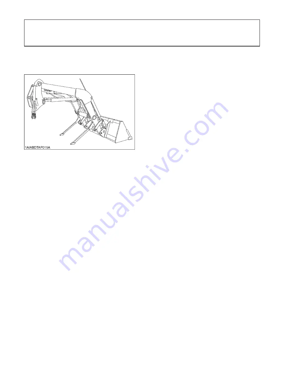
STORING THE LOADER

STORING THE LOADER

1. Store the loader in a clean dry place.
2. Make sure the loader is properly supported.
3. Attach the protective plugs and caps to the couplers to

protect them from dust.

4. Check all hydraulic hoses and connections. Repair or

replace them if necessary.

5. Repair or replace any worn, damaged or missing

parts.

6. Lubricate loader as described in "LUBRICATION" in

Maintenance section.

7. Apply a coat of grease to all exposed cylinder rods and

mounting pins to prevent rust.

8. Repaint worn or scratched parts.

Summary of Contents for LA1954

Page 1: ......

Page 2: ...California Proposition 65 Cancer and Reproductive Harm www P65Warnings ca gov WARNING ...

Page 3: ...will have the most up to date information Please do not hesitate to consult with them 3SAFETY FIRST This symbol the industry s Safety Alert Symbol is used throughout this manual and on labels on the machine itself to warn of the possibility of personal injury Read these instructions carefully It is essential that you read the instructions and safety regulations before you attempt to assemble or us...

Page 4: ...2 FILLING THE BUCKET 12 LIFTING THE LOAD 13 CARRYING THE LOAD 13 DUMPING THE BUCKET 13 LOWERING THE BUCKET 13 OPERATING WITH FLOAT CONTROL 14 LOADING FROM A BANK 14 PEELING AND SCRAPING 15 LOADING LOW TRUCKS OR SPREADERS FROM A PILE 15 BACKFILLING 16 HANDLING LARGE HEAVY OBJECTS 16 VALVE LOCK 17 Valve Lock 17 BUCKET LEVEL INDICATOR 17 BOOM CYLINDER FULCRUM 17 SELF LEVELING if equipped 18 FRONT REM...

Page 5: ...NANCE 29 ATTACHMENTS 30 Quick attach bucket 30 Bale spear 30 Pallet fork 31 ASSEMBLE PALLET FORK 31 MAINTENANCE 32 LUBRICATION 32 RE TIGHTENING OF HARDWARE 32 DAILY CHECKS 32 EVERY 50 HOURS 33 Checking main frame bolt torque 33 General torque specification 34 REMOVING THE LOADER 35 STORING THE LOADER 37 REINSTALLING THE LOADER 38 ...

Page 6: ...vent accidental actuation when the implement is not in use or during transport Do not utilize the valve lock for machine maintenance or repair 8 Assemble remove and reinstall the loader only as directed in this manual Failure to do this could result in serious personal injury or death 9 Follow the precautions below when attaching attachments Quick attach coupler A Make sure both handles LH RH cont...

Page 7: ...le Doing so could cause a rollover or serious damage to the loader 18 Be extra careful when operating the tractor on a slope always operate up and down never across the slope Do not operate on steep slopes or unstable surfaces 19 When operating another implement on a hillside be sure to remove the loader to reduce the risk of rollover 20 Carry loader boom at a low position during transport You sho...

Page 8: ...3 SAFE OPERATION DANGER WARNING AND CAUTION LABELS ...

Page 9: ...SAFE OPERATION 4 ...

Page 10: ...ft cloth 3 Replace damaged or missing danger warning and caution labels with new labels from your local KUBOTA dealer 4 If a component with danger warning and caution label s affixed is replaced with new part make sure new label s is are attached in the same location s as the replaced component 5 Mount new danger warning and caution labels by applying on a clean dry surface and pressing any bubble...

Page 11: ......

Page 12: ...self However when in need of parts or major service be sure to see your KUBOTA dealer For service contact the KUBOTA dealership from which you purchased your loader or your local KUBOTA dealer When in need of parts be prepared to give your dealer the loader serial number Locate the serial numbers now and record them in the space provided KUBOTA LOADER Model Serial Number Date of Purchase Name of D...

Page 13: ... One Detent Float Position Power Beyond Circuit RATED FLOW L m GPM 68 18 0 MAXIMUM PRESSURE MPa kg cm psi 20 7 211 3002 NET WEIGHT APPROXIMATE kg lbs 898 1980 LOADER MODEL LA2254 TRACTOR MODEL M126GX M135GX WHEEL BASE WB mm in 2690 105 9 FRONT TIRES 14 9 R24 REAR TIRES 18 4 R38 BOOM CYLINDER BORE mm in 75 2 95 STROKE mm in 680 26 8 BUCKET CYLINDER BORE mm in 75 2 95 STROKE mm in 610 24 CONTROL VAL...

Page 14: ... 43 1000 39 37 CAPACITY STRUCK m CU FT 0 52 18 4 0 63 22 3 HEAPED m CU FT 0 64 22 6 0 79 27 9 WEIGHT kg lbs 235 518 255 562 LOADER MODEL LA1954 LA2254 MODEL SQUARE 96 LIGHT MATERIAL 96 TYPE QUICK ATTACH WIDTH mm in 2440 96 DEPTH L mm in 665 26 2 800 31 5 HEIGHT M mm in 750 29 5 764 30 1 LENGTH N mm in 770 30 3 910 35 8 CAPACITY STRUCK m CU FT 0 66 23 3 0 80 28 3 HEAPED m CU FT 0 75 26 5 0 98 34 6 ...

Page 15: ...GHT UNDER LEVEL BUCKET mm in 3470 136 6 3160 124 4 3862 152 3527 138 9 C CLEARANCE WITH BUCKET DUMPED mm in 2860 112 6 2490 98 0 3290 129 5 2956 116 4 D REACH AT MAX LIFT HEIGHT DUMPING REACH mm in 489 19 3 864 34 0 761 30 0 1157 45 5 E MAX DUMP ANGLE deg 52 63 50 60 F REACH WITH BUCKET ON GROUND mm in 2230 87 8 2434 95 8 G BUCKET ROLL BACK ANGLE deg 40 H DIGGING DEPTH mm in 60 2 4 65 2 6 131 5 2 ...

Page 16: ...CITY 800 mm FORWARD 1500 mm HEIGHT kg lbs 1575 3472 1840 4057 1967 4337 2173 4791 Y BREAKOUT FORCE BUCKET PIVOT PIN N lbf 24860 5589 29250 6576 29273 6585 33957 7639 Z BREAKOUT FORCE 800 mm FORWARD N lbf 17190 3864 22200 4991 21687 4879 25147 5657 VV BUCKET ROLL BACK FORCE AT MAX HEIGHT N lbf 13720 3084 16080 3615 17627 3965 20451 4601 XX BUCKET ROLL BACK FORCE AT 1500 mm HEIGHT N lbf 25860 5814 2...

Page 17: ...6 SPECIFICATIONS LA1954 For greatest power For greatest lift ...

Page 18: ...7 SPECIFICATIONS LA2254 For greatest power For greatest lift ...

Page 19: ...SPECIFICATIONS 8 LOADER TERMINOLOGY 1 Mounting pin 2 Side frame 3 Hydraulic control valve 4 Boom cylinder 5 Main frame 6 Boom 7 Bucket cylinder 8 Bucket 9 Control lever ...

Page 20: ...A To check the tractor transmission fluid level lower the bucket to the ground and lower the 3 point hitch TREAD 1 Set the front tread as follows A Setting the tread wider than recommended may cause premature failure of the front axle components due to excessive stress 2 For better stability set the rear tread as follows depending on the requirements of the work being done 1 Dipstick 2 Oil inlet A...

Page 21: ...fer to the tractor operator s manual for optional tires BInflation pressure Implement as Counter Weight 6 Box Scraper Approx 450 kg 992 lbs Rotary Tiller Approx 240 kg 529 lbs Tire sizes 16 9 34 18 4R30 18 4 30 18 4R34 18 4R38 520 70R38 Slush free at 10 14 Solid at 30 22 Approx 1 kg 2 lbs CaCl per 4 L 1 gal of water 342 kg 755 lbs 385 kg 848 lbs 417 kg 920 lbs 460 kg 1013 lbs Slush free at 24 11 S...

Page 22: ...ately A When the lever is at each corner position marked by asterisk or lower left boom and bucket cylinders work at the same time However the lower left position Raise Roll back is not recommended for scooping because of insufficient lift force To begin a test operation slightly move the control lever from the N position Slowly raise the loader boom just enough for the bucket to clear the ground ...

Page 23: ...not recommended that the loader be attached when operating another implement on a hillside A Before operating the loader in rough terrain remove the mower to avoid damage to the mower FILLING THE BUCKET Approach and enter the pile with a level bucket Ease control lever toward you and then left to rollback and lift the bucket The rollback and lifting of the bucket will increase efficiency because a...

Page 24: ... operating the loader on a slope Keep the bucket as low as possible This keeps the bucket and tractor center of gravity low and will provide maximum tractor stability To avoid serious personal injury A Be extra careful when working on inclines A When operating on a slope always operate up and down the slope never across the slope When transporting a load keep the bucket as low as possible to avoid...

Page 25: ...that provides a safe ground speed and power for loading To avoid serious personal injury A Be extra careful when working on inclines A When operating on a slope always operate up and down the slope never across the slope A Loader lift and break away capacity diminish as loading height is increased Side cutting is a good technique for cutting down a big pile Wheel width should not exceed the bucket...

Page 26: ...linder to maintain proper depth Make additional passes until the desired depth is reached During each pass use only the bucket control while at working depth This will allow you to concentrate on controlling the bucket angle to maintain a precise cut LOADING LOW TRUCKS OR SPREADERS FROM A PILE For faster loading minimize the angle of turn and length of run between pile and spreader Backgrade occas...

Page 27: ...t on the high side for easier backfilling on a slope HANDLING LARGE HEAVY OBJECTS To avoid serious personal injury or death A Handling large heavy objects can be dangerous due to A Danger of rolling the tractor over B Danger of upending the tractor C Danger of the object rolling or sliding down the loader boom onto the operator A If you must perform the above work protect yourself by A Not lifting...

Page 28: ...front attachment loosen the indicator rod lock bolt and readjust the indicator rod length BOOM CYLINDER FULCRUM A Before repositioning the boom cylinder fulcrum place the front attachment in contact with a flat ground This loader is provided with two boom cylinder fulcrums A and B The top fulcrum A is used when more lifting height is needed The bottom fulcrum B is employed when more lifting force ...

Page 29: ...r K9059 48 Pallet Forks M1804 Quick Attach Bale Spear A Recommended engine revolution above 1200 rpm A Warm up the tractor according to its instructions before moving the loader in cold regions This is needed to prevent a valve malfunction In the self leveling mode A Boom lowering speed will be slower A Boom cannot be lowered in the maximum roll back position A Boom cannot be raised in the maximum...

Page 30: ... pallet fork operation The pallet fork can be raised up and lowered horizontally b For bucket operation The bucket position can be controlled like Spill Guard 2 Self Leveling is OFF Motion is same as the regular loader a For pallet fork operation b For bucket operation ...

Page 31: ...l line of the jig marked V the pallet fork is flat 4 Raise the boom to the maximum height 5 If the pallet fork angle is not within the angle shown in the illustration readjust the self leveling A When the pendulum indicates the white range of the jig the pallet fork angle is proper 6 If the pallet fork angle is not within the angle shown in the illustration lower the boom and loosen the lock nut t...

Page 32: ... fork angle is not within the angle shown in the illustration readjust the self leveling A When the pendulum indicates the white range of the jig the bucket or pallet fork angle is proper 4 If the bucket or pallet fork angle is not within the angle shown in the illustration loosen the lock nut then adjust by setscrew as follows Pallet fork forward tilt Screw OUT Pallet fork back tilt Screw IN Typi...

Page 33: ...lic valve main switch Push the front hydraulic valve main switch 1 to engage the front hydraulic valve A light on the switch will illuminate to indicate that the front hydraulic valve is on and to enable the activation switch 2 2 Activation switch 1 When pressing the A button hydraulic oil will come out of Port A and return through Port B as long as the switch is pressed 2 When pressing the B butt...

Page 34: ...the front hydraulic valve main switch ON 3 Press the activation switch A and B several times 4 Push the front hydraulic valve main switch OFF 5 Turn the key switch to the OFF position C Connecting 1 Clean both couplers 2 Remove dust plugs 3 Insert the implement coupler to the tractor hydraulic coupler 4 Pull the implement coupler slightly to make sure couplers are firmly connected C Disconnecting ...

Page 35: ...pressure from the accumulator A When it is necessary to move the loader more precisely keep the KSR system off It is particularly advisable to keep it off for handling pallets in which the loader must be accurately moved MULTI COUPLER SYSTEM if equipped This system is designed to easily connect and disconnect the four hydraulic hoses simultaneously without oil leak when attaching and detaching the...

Page 36: ... lever downward until it stops and close the dust cover To avoid machine damage A Before connecting each ensure to carefully clean the mating surfaces of the fixed part of the mobile part and the reference pins A Lubricate periodically all the moving components A Once the mobile part is disconnected please close the dust cover to keep the flat surface of the fixed part clean 1 Mobile part 2 Refere...

Page 37: ...l the way up to ensure that the latching pins are fully retracted 2 Position the tractor squarely in front of the attachment and tilt the quick attach coupler forward with the bucket cylinders 3 Ease the quick attach coupler mounting plate into the saddle of the attachment 4 Roll the quick attach coupler back using the bucket cylinders and raise the boom slightly The back of the attachment should ...

Page 38: ... are met 6 Visually verify when pushing the quick attach coupler handles into locked position that the latch pins rotate completely and are located underneath the stop of the quick attach coupler 7 When attaching different attachments visually inspect for broken or damaged pins If broken or damaged pins are found replace before using Use of broken pins may result in attachment detachment or deform...

Page 39: ...upler pin to the unlocked position Tilt the quick attach coupler forward slightly 2 Adjust the quick attach coupler angle as shown in the figure Drive the tractor forward slowly to position the quick attach coupler under the attachment hooks Now these hooks are visible from the direction of arrow 3 When the quick attach coupler comes in contact with the attachment raise the loader to hook the impl...

Page 40: ...position to prevent damage to the handle assembly BEuro type coupler 1 Lower the attachment to ground level with the attachment slightly in the rolled back position Stop the engine and set the parking brake 2 Shift the handle of the quick attach coupler pin to the unlocked position 3 Start the engine and slowly move the loader control lever to the LOWER position until the attachment disengages fro...

Page 41: ...CK CAPACITY 0 66 cu m 23 3 cu ft LIGHT MATERIAL 96 WIDTH 2400 mm 96 in STRUCK CAPACITY 0 80 cu m 28 3 cu ft BBale spear OVERALL HEIGHT 602 mm 23 70 in OVERALL WIDTH 1215 mm 47 83 in OVERALL LENGTH INCLUDING MAIN SPEAR 980 mm 38 58 in USEABLE LENGTH OF MAIN SPEAR 640 mm 25 20 in USEABLE LENGTH OF SPEAR 2 355 mm 13 98 in MAXIMUM DIAMETER OF MAIN SPEAR 45 mm 1 77 in DIAMETER OF SPEAR 2 32 mm 1 26 in ...

Page 42: ...enter notch of the frame 2 Slide the fork to the desired position 3 Push the lock lever and slide the fork slightly until the lock pin engages with one of the notches to lock the folk 4 The other fork can be installed using the same procedures Loader Model Rated Capacity LA1954 930 kg 2050 lbs LA2254 1090 kg 2400 lbs 1 Fork 1 Fork 1 Lock lever ...

Page 43: ...DAILY CHECKS 1 Before the day s operation visually check to see if the hardware and their bolts and nuts are tight enough 2 With the engine off and the bucket on the ground inspect all hoses for cuts or wear Check for signs of leaks and make sure all fittings are tight To avoid serious personal injury A Escaping hydraulic fluid under pressure can have sufficient force to penetrate skin causing ser...

Page 44: ...BChecking main frame bolt torque To avoid personal injury A Never operate front loader with a loose main frame A Any time bolts and nuts are loosened retighten to specified torque A Check all bolts and nuts frequently and keep them tight Check main frame bolts and nuts regularly especially when new If they are loose tighten them as follows 1 Tightening torque 319 N m 32 5 kgf m 235 ft lbs 2 Tighte...

Page 45: ... 84 to 5 81 35 0 to 42 0 61 0 to 73 2 6 22 to 7 46 45 0 to 54 0 M10 N m kgf m ft lbs 48 1 to 55 8 4 9 to 5 7 35 5 to 41 2 1 2 N m kgf m ft lbs 108 5 to 130 2 11 06 to 13 28 80 0 to 96 0 149 2 to 179 0 15 21 to 18 25 110 0 to 132 0 M12 N m kgf m ft lbs 77 5 to 90 1 7 9 to 9 2 57 2 to 66 5 9 16 N m kgf m ft lbs 149 2 to 179 0 15 21 to 18 25 110 0 to 132 0 217 0 to 260 4 22 13 to 26 55 160 0 to 192 0...

Page 46: ...re aligned Then slide the stands outward and insert the spring pin as shown 5 Start the engine and run at idle 6 Dump the bucket approximately 20 degrees 7 Lower the boom and raise the front wheels slightly A Lift the weight off the front wheels with the bucket Do not attempt to lift them with the stands 8 Stop the engine 9 Remove the mounting pins from the loader main frame and hold them on boom ...

Page 47: ...er tilting the connector assy stay to make space between muffler and quick coupler 15 Place the protective caps and plugs on the quick coupler ends 16 Start the engine and slowly back the tractor away from the loader 1 Connecter assy stay 1 Protective plug ...

Page 48: ...to the couplers to protect them from dust 4 Check all hydraulic hoses and connections Repair or replace them if necessary 5 Repair or replace any worn damaged or missing parts 6 Lubricate loader as described in LUBRICATION in Maintenance section 7 Apply a coat of grease to all exposed cylinder rods and mounting pins to prevent rust 8 Repaint worn or scratched parts ...

Page 49: ...ove the hydraulic control lever to dump position to lower the side frames into the main frames and engage the bosses of the side frames to the guide plates of the main frames Then lift the weight off the front wheels with the loader do not lift the wheels off the ground A Do not attempt to lift the front wheels with the stands 6 Stop the engine Reinstall the mounting pins and secure them with the ...

Page 50: ...ABBREVIATION LIST ...

Reviews: