background image

107

LIST OF SCREENS

LIST OF SCREENS

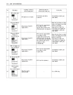
LIST OF NORMAL SCREENS

No.

Message

Problem or failure

(What happened)

Machine behavior

(Provisional measure)

Correction

1

Glow screen

This screen indicates that
the glow lamp is on.

Wait until the glow mark
disappears. Then get the
engine started.

-

2

Default screen 

(normal)

This screen shows the
normal status. (Hour meter)

-

-

3

Default screen 

(normal) 

Tachometer (numeric) This screen shows the

normal status. (Numerical
display of tachometer
readings)

-

-

4

AUX port enable 

switch activated

(hour meter)

AUX port enable screen

-

-

5

AUX port enable 

switch activated

Tachometer (numeric)

AUX port enable screen

-

-

Summary of Contents for KX080-4S

Page 1: ...0 Malaysia KUBOTA MALAYSIA SDN BHD No 3 Jalan Sepadu 25 123 Taman Perindustrian Axis Seksyen 25 40400 Shah Alam Selanɡor Darul Ehsan Malaysia Telephone 60 3 736 1388 Philippines KUBOTA PHILIPPINES INC 232 Quirino Hiɡhway Baesa Quezon City 1106 Philippines Telephone 63 2 422 3500 Taiwan SHIN TAIWAN AGRICULTURAL MACHINERY CO LTD 16 Fenɡpinɡ 2nd Rd Taliao Shianɡ Kaohsiunɡ 83107 Taiwan R O C Telephone...

Page 2: ...s the boom and dozer High speed International Organization for Standardization Japanese Industry Standard Volume Liter Liter per minute Low speed Mass Air Flow Military Standard Operator Protective Guards Occupational Safety and Health Administration Pressure Limiter Positive Crankcase Ventilation Roll Over Protective Structure Revolutions Per Minute Society of Automotive Engineers USA Two Pattern...

Page 3: ...rowd Bucket crowd Bucket dump Boom swing Left Boom swing Right Dozer raise Dozer lower Operation direction of control lever Operation direction of control lever Read operator s manual Lock Unlock Engine stop control lamp ECO mode Energy saving mode GENERAL SYMBOLS The instruments and operation elements have been marked with a series of symbols in order to simplify the opera tion of your excavator ...

Page 4: ...ates a potentially hazardous situation which if not avoided could result in minor or moderate injury Indicates that equipment or property damage could result if instructions are not followed This symbol the industry s Safety Alert Symbol is used throughout this manual and on labels on the machine itself to warn of the possibility of personal injury Read these instructions carefully It is essential...

Page 5: ...layed at a Glance on a Single Screen 16 When the Check up is Completed 18 Horn Switch 18 Light Switch 18 AUX Port Flow Rate Limit Switch 18 Auto Idle Control Switch 19 Throttle Potentiometer 19 Travel Speed Switch 19 Inhibit Diesel Particulate Filter DPF Regeneration Switch 20 Beacon Light Switch 20 ECO MODE 21 CAB TYPE MACHINES 21 Wiper Washer Switch 21 Interior Lamp 21 Heater Switch 22 Opening C...

Page 6: ... 35 UP AND DOWNHILL DRIVING 36 PARKING ON A SLOPE 36 OPERATION OF THE DOZER 36 TWO PATTERN SELECTION SYSTEM TPSS 37 Pattern Change 37 OPERATION OF THE BOOM 38 OPERATION OF THE ARM 38 OPERATION OF THE BUCKET 39 UNIT SWING AND BOOM SWING OPERATION 39 Unit Swing Operation 39 Boom Swing Operation 39 AUXILIARY PORT OPERATION 40 Selecting the Action Modes 40 AUX Port Handling Procedure 41 Setting the Ma...

Page 7: ...ler 71 REGULAR CHECKS AND MAINTENANCE WORK 72 EVERY 50 SERVICE HOURS 72 Draining the Water from the Fuel Tank 72 Draining Water Separator 72 Battery 73 Battery Charging 74 Greasing Swing Bearing Teeth 74 EVERY 100 SERVICE HOURS 74 Greasing Boom Swing Fulcrum 74 EVERY 200 SERVICE HOURS 75 Adjusting V belt Tension 75 Checking Radiator Hoses and Clamps 76 Grease Swing Ball Bearing 76 Inspection and C...

Page 8: ...al Circuit 86 Checking Air Conditioner Pipes and Hoses 86 Checking Boost Sensor and AFS Air Flow Sensor 86 Checking Condition of Diesel Particulate Filter DPF Muffler 86 Checking Diesel Particulate Filter DPF Differential Pressure Sensor and Piping for Gas Leak 86 Checking Diesel Particulate Filter DPF Exhaust Gas Temperature Sensor 86 Checking EGR Piping for Gas Leak 86 BIENNIAL SERVICING 87 Repl...

Page 9: ...TION FOR OPERATION IN COLD WEATHER 97 PROCEDURE AFTER COMPLETING WORK 97 LONG STORAGE 98 RECOMMENDED OILS 100 BIODIESEL FUEL BDF 102 APPENDICES 104 MAIN DIMENSIONS 104 LIFTING CAPACITY 105 LIST OF SCREENS 107 LIST OF NORMAL SCREENS 107 NAVIGATION LIST OF SCREENS 108 AUTOMATIC DIESEL PARTICULATE FILTER DPF REGENERATION 116 LOCKING AND RELEASING THE DIESEL PARTICULATE FILTER DPF REGENERATION 117 ...

Page 10: ......

Page 11: ...Level I as this combination will reduce the risk of serious injury or death should the excavator be upset or falling objects occur Do not modify any structural members of the ROPS OPG Top Guard Level I by welding drilling bending grinding or cutting as this may weaken the structure If any component is damaged replace it Do not attempt repairs If the ROPS OPG Top Guard Level I is loosened or remove...

Page 12: ...operator must remain in the excavator seat during operation 13 Check levers pedals and all mechanical parts for correct adjustment and wear Replace worn or damaged parts immediately Check nuts and bolts regularly for correct torque 14 Keep your excavator clean Heavy soiling grease dust and grass can cause fires accidents or injuries 15 Use only KUBOTA authorized attachments 16 Before starting the ...

Page 13: ...direction of the drive levers C Working 1 Do not operate or idle engine in a non ventilated area Carbon monoxide gas is colorless odorless and deadly If you experience the initial symptoms of low to moderate co poisoning which include the following stop operation seek medical attention and contact your local dealer These symptoms are headache fatigue shortness of breath nausea or dizziness 2 Keep ...

Page 14: ...rom silica dust Avoid exposure to dust containing crystalline silica particles This dust can cause serious injury to the lungs silicosis Because crystalline silica is a basic component of sand and granite many activities at construction sites produce dust containing crystalline silica Trenching sawing and boring of material containing crystalline silica can produce dust containing crystalline sili...

Page 15: ...and robust ramps when loading on the machine for details see TRANSPORTING THE EXCAVATOR ON A VEHICLE 3 Do not change the running direction and to avoid tipping over do not try to swing the attachment crosswise to the loading ramps 4 Lower the attachment on the loading bed and release the pressure from the hydraulic system Stop the engine and remove the key After loading the excavator on the truck ...

Page 16: ...TERY in OPERATION OF THE ENGINE when starting with an auxiliary battery 6 Keep a first aid box and a fire extinguisher at hand at all times 7 Do not open the radiator cap before the radiator has cooled down sufficiently First loosen the cap to the first stop and allow the system enough time to release the remaining pressure Then loosen the cap completely 8 To avoid short circuiting the battery alw...

Page 17: ...keep the risk of fire to a minimum A Before proceeding to regenerate the DPF a warning indicator appears on the LCD display to tell you to increase the engine rpm to its specified level Follow that instruction A When the Diesel Particulate Filter DPF is in the regenerating cycle the exhaust gas and the DPF muffler become hot During regeneration take into account that the exhaust gas and muffler wi...

Page 18: ...SAFE OPERATION 8 ...

Page 19: ... 9 SAFE OPERATION ...

Page 20: ...SAFE OPERATION 10 ...

Page 21: ... 11 SAFE OPERATION ...

Page 22: ...SAFE OPERATION 12 ...

Page 23: ... 13 SAFE OPERATION ...

Page 24: ... danger warning and caution labels with new labels from your KUBOTA dealer 4 If a component with danger warning and caution label s affixed is replaced with new part make sure new label s is are attached in the same location s as the replaced component 5 Mount new danger warning and caution labels by applying on a clean dry surface and pressing any bubbles to outside edge 7 CARE OF DANGER WARNING ...

Page 25: ... the warranty period The Product s described in this Operator s Manual are designed and manufactured only for the country in which they are initially wholesaled by KUBOTA or one of its affiliated companies Neither KUBOTA Corporation nor its affiliated companies provide warranty for any Product which is re sold or retailed in any country other than the country for which the Product s were designed ...

Page 26: ...DEALER SERVICE 2 1 Engine serial No ...

Page 27: ...20 8770 19330 Engine Type Water cooled 4 cycle diesel engine with 4 cylinder Model name KUBOTA V3307 CR TE4 Total displacement cc cu in 3331 203 3 Engine power SAE gross kW Hp 49 7 66 6 SAE net kW Hp 46 5 62 3 Rated speed rpm 2000 Low idling speed rpm 1100 Performance Unit swing speed rpm 10 2 Travel speed Fast km h mph 4 8 3 0 Slow km h mph 2 7 1 7 Ground kPa pressure kgf With operator 75 kg psi ...

Page 28: ... CONTENTS 1 Arm 2 Bucket cylinder 3 Bucket link 2 and 3 4 Bucket link 1 5 Bucket 6 Boom cylinder 7 Dozer cylinder 8 Dozer blade 9 Arm cylinder 10 Boom 11 Working light 12 Cabin 13 Operator s seat 14 Swing bracket 15 Track 16 Drive sprocket 17 Front idler 18 Angle blade ...

Page 29: ... DPF inhibit switch 11 Beacon light switch Ref page Starter switch 7 LCDdisplay 8 Fuel gauge Water temperature gauge Hour meter Engine tachometer Glow lamp User setting switch AUX port enable switch Information switch Display selector switch 8 Warninglamp 11 12 User setting switch Switch 1 13 Switch 2 14 AUX port enable switch Switch 3 15 Information switch Switch 4 16 Display selector switch Swit...

Page 30: ...lever left 3 Boom swing pedal 4 Drive lever right 5 Attachment control lever right 6 Dozer control lever 7 Drive pedal left 8 Drive pedal right Ref page Drive lever left 34 Attachment control lever left 38 39 Boom swing pedal 39 Drive lever right 34 Attachment control lever right 38 39 Dozer control lever 36 ...

Page 31: ...BELS in SAFE OPERATION section Inspect ROPS OPG Top Guard Level I for damage and if damage is found contact your KUBOTA dealer for repair CHECKING THE DEVICES BStarter Switch A STOP The key can be inserted at the STOP position A RUN Turn the key one click from the STOP position to the RUN position All the circuitry gets energized to start preheating The glow indicator is displayed To check for any...

Page 32: ...for 10 seconds BLCD Display for Normal Operation C Fuel gauge To avoid personal injury or death A Before adding fuel be sure to stop the engine A Be sure to keep open flame away from the machine Otherwise a fire may result With the starter key at the RUN position the fuel remaining in the fuel tank is indicated in the block If the fuel runs short open the cap and refuel the tank A If the fuel gaug...

Page 33: ... Fan belt tension 3 Mud or dust deposits on radiator 4 Hydraulic oil leak C Overheat warning 1 If the coolant temperature becomes too high the message Water temp is Rising appears onscreen for a certain period of time The LCD then gets back to normal but the coolant temperature sensor marker starts blinking at 1 second intervals A If this message is displayed the EGR valve will begin to close and ...

Page 34: ... warning lamp is used to indicate broken wire short circuit fuel shortage and other problems The warning lamp starts flashing in red if any problem occurs If the system senses a in warning signal the warning lamp starts flashing in yellow A If the warning illuminates do not just look at the meter carry out the appropriate inspection and correction accordingly See REGULAR CHECKS AND MAINTENANCE WOR...

Page 35: ...e RUN position without starting the engine and the charging lamp stays off the charging system has failed If such occurs immediately contact your local dealer for repair C Engine oil pressure low warning When the engine oil pressure drops too low the lamp red starts flashing and the following message appears in the display Immediately stop the engine and check the engine oil level A If the starter...

Page 36: ...ormation switch and a detail such as shown below appears A Press the information switch again and the display goes back to the previous screen A If you have any question consult your KUBOTA Dealer BSetting the Clock 1 Turn the starter key to the RUN position 2 Press the switch 1 to make the log record periodic check clock set screen appear 1 Information switch User settings 1 Starter switch A STOP...

Page 37: ...month day hour and minute will be selected in this order 4 Save the new setting with the switch Switch 5 Press this switch 5 again to set the clock Status after setting the clock A Be careful not to accidentally press the switch 5 on the clock setting screen Otherwise the seconds will be set to 00 and the clock will show the wrong time A When the user setting switch Switch 1 is pressed on the cloc...

Page 38: ...dered 2 Using the switch 4 move the cursor to Side B Select the AM PM system or the 24 hour system 3 Press the switch 5 and the new settings will be made If the switch 1 is pressed the previous settings will remain BLog Record The log record helps you check the last 3 month operating record of the machine Take the following steps 1 Set the starter key to the RUN position 2 Press the switch 1 to ma...

Page 39: ... BPeriodic Check The following message appears on the LCD 10 hours before a periodic check Press the switch 4 to see the check results Do the following servicing listed below A When the servicing has been completed turn the key switch ON and OFF 10 times or more and the check screen automatically disappears A When the periodic check interval has passed the message Periodic Check Passed shows up Im...

Page 40: ... START 16 BIf All the Check Points are not Displayed at a Glance on a Single Screen 1 Press the switch 4 2 Each time the switch 2 or 3 is pressed the check points scrolled up or down 1 Switch 4 2 Switch 2 3 Switch 3 ...

Page 41: ...CJ 4 change every 500 hrs 2 Hydraulic oil every 1000 hrs 3 Air filter element Outer element replace every 1000 hrs Inner element every 1000 hrs 4 Fuel filter every 500 hrs 5 Engine oil filter every 500 hrs 6 Drive unit oil change every 500 hrs 7 Hydraulic return filter cartridge replace every 1000 hrs 8 Hydraulic suction filter element every 1000 hrs 9 Pilot filter replace every 1000 hrs 10 Idler ...

Page 42: ...previous screen BHorn Switch BLight Switch When the starter switch is in position RUN the working light s and CAB light s will be switched on by pressing the switch C Night operation To avoid personal injury or death A When the working light and CAB light alone do not provide sufficient visibility prepare additional stationary artificial lighting and observe safety rules for night work BAUX Port F...

Page 43: ...l speed switch The buzzer beeps twice and the travel speed changes from low to high The symbol lights up 2 Press the travel speed switch again and the buzzer beeps once and the travel speed changes from high speed to low The symbol goes out A When activating the travel speed switch it must be pushed down completely A Each time the travel speed switch is pressed the travel speed is switched between...

Page 44: ...achine in this condition BInhibit Diesel Particulate Filter DPF Regeneration Switch Inhibit Diesel Particulate Filter DPF regeneration switch hereinafter called inhibit switch disables the Auto DPF regeneration cycle Activate this switch to turn off Auto DPF Regeneration when working around people animals plants and flammable materials Certain work conditions may require the Auto DPF regeneration ...

Page 45: ... the starter key is in the RUN position A further push on the switch will activate the washer system Even when the wiper switch is in the OFF position the washer switch functions if it is pressed A Do not activate the washer switch if the tank for the cleaning fluid is empty the pump can be damaged A Do not activate the wiper switch if the window is dry In this case make sure that cleaning fluid i...

Page 46: ...on A During summer turn the heater valve clockwise to close the valve BOpening Closing of CAB Door 1 Unlock the CAB door and pull the knob Open the CAB door fully until fixed into place 2 To close the CAB door push the release lever down and close the door 3 When leaving the excavator always lock the door 1 Heater switch 2 Temperature control dial 1 Door knob outside 1 Release lever 2 Door knob in...

Page 47: ...rself to let the windshield slide inward 3 Pull the windshield all the way to the lock at the back of CAB 4 To close the window take the reverse steps 3 2 and 1 BOpening Closing of Side CAB Window 1 Pull the grip to release the lock and pull side window open to the rear or to the front 2 To close the side window slide it forward or backward until the lock snaps in at the window frame BEmergency Ha...

Page 48: ...ot allow water to enter the fresh air port while washing the excavator BAir Control Vent C Front air outlet The front air outlets can be independently adjusted as required To defrost the windshield rotate the outlets toward the windshield A FRONT WINDOW B CHEST AREA C FOOT AREA D SIDE WINDOW E BACKWARD 1 Inlet selector lever A FRESH AIR INLET position B INNER AIR RECIRCULATION position C FRESH AIR...

Page 49: ...ial to the COOL or an intermediate position to achieve the desired temperature level A Be sure to close the door while the air conditioner is ON otherwise you may overload the compressor C Cooling 1 Press and turn on the air conditioner switch 2 Turn on the blower 1 2 3 switch 3 Adjust the temperature control dial to the COOL or an intermediate position to achieve the desired temperature level C D...

Page 50: ...er for more than 10 sec A If the engine does not start in 10 sec please wait 20 sec or more before attempting to restart STARTING THE ENGINE To avoid personal injury or death A The operator should not depend solely on the warning lamps but should always conduct the routine checks see MAINTENANCE Start the engine in the following manner 1 Before starting the engine make sure that all control levers...

Page 51: ... is dead and must be connected to another battery with jumper cable be sure to use a 12V battery Never use 24V batteries A If you keep the pilot control lock lever at UNLOCK and try to start the engine Up Lever Lock appears on the meter panel and the engine cannot be started Before staring the engine make sure the pilot control lock lever is set at the LOCKED position A When the engine starts the ...

Page 52: ...ury or death A Battery gases can explode Do not smoke and keep sparks and flames away A Do not start the engine with an auxiliary battery if excavator battery is frozen A Do not connect the black jumper cable to the negative terminal of the excavator battery BObserve Following Guidelines when Starting with an Auxiliary Battery 1 Bring the helping machine with the same battery voltage as near as po...

Page 53: ... minutes This allows the engine lubricant to warm up and penetrate every part of the engine 2 Once the engine has warmed up check A the warning lamp Engine oil pressure has gone out A the warning lamp Battery charge goes out when engine speed is increased A the color of the exhaust is normal and no abnormal noises or vibrations are heard or felt A no fluid is leaking from pipes or hoses C Should a...

Page 54: ...gine or overflow for 10 minutes or until the steam overflow stops 4 Be sure that there is no danger of getting scalded Pinpoint and remove the cause of overheat referring to the TROUBLESHOOTING section Once the issue is resolved the engine may be restarted BDPF Regeneration This machine is equipped with a DPF Diesel Particulate Filter muffler DIESEL PARTICULATE FILTER serves to trap particulate ma...

Page 55: ... so many fine metal particles are generated which can cause damage and shorten the life of many components Pay attention to the oil change intervals and complete them sooner than later See REGULAR CHECKS AND MAINTENANCE WORK section for more details on the oil change intervals BAdjusting the Operator s Seat To avoid personal injury or death A Make sure that the seat is completely secured after eac...

Page 56: ...hands and body inside of the ROPS OPG Top Guard Level I protective A Do not touch the control levers and the pedals from outside the cab while the engine running BPilot Control Lock Lever To avoid personal injury or death A To avoid injuries check safety aspects all around the excavator A If the pilot control lock lever is pulled down the engine will fail to start Don t attempt to start the machin...

Page 57: ...ront of the excavator A Use extra caution when traveling across a slope or working sideways on a slope A Recommended technique for working on a slope 1 Adjust the engine speed from idling to an intermediate speed 2 Unlock the pilot control lock lever and pull in the bucket and hold the bucket about 20 to 40 cm 8 to 16 in above the ground A Front of the excavator 1 Pilot control lock lever A UNLOCK...

Page 58: ...xcavator forwards and vice versa The front of the excavator is the side where the dozer is located the drive sprocket is in the rear of the excavator TURNS To avoid personal injury or death A Do not change direction on steep slopes or the excavator could tip over A Before changing direction beware of people in the work area BPivot Turn A Movement as illustrated is done with the dozer blade in fron...

Page 59: ...cavator will turn in the direction of the arrow of the illustration below 2 Pull the left drive lever backward the excavator will turn in the direction of the arrow of the illustration below BSpin Turn When both drive levers are activated in the opposite directions both tracks will rotate with the same speed but in opposite directions The center of rotation is the center of the excavator B Travell...

Page 60: ...ING DOWNHILL TRAVELING PARKING ON A SLOPE To avoid personal injury or death A When the excavator is parked or left unattended on a slope be sure to put the tip of bucket into ground and place all control levers in neutral position then brace the tracks with chocks OPERATION OF THE DOZER 1 To raise the dozer pull back the control lever To lower the dozer push the control lever forward To float the ...

Page 61: ...pen the cover and position the pattern selector lever to the desired position 2 Close the cover 1 Pattern selector lever Two Pattern Selection System TPSS A Pattern A B Pattern B Lever Position Attachment Control Lever Left Attachment Control Lever Right Pattern A A B C D Boom down Boom up Swing left Swing right Arm out up Arm in crowd Bucket crowd Bucket dump Pattern B A B C D Arm out up Arm in c...

Page 62: ...he oil warms up To lower the boom push the attachment control lever forward A When lowering the boom make sure that it does not hit the dozer and that the bucket teeth do not touch the dozer OPERATION OF THE ARM Pull back the attachment control lever and the arm will be pulled in To move the arm out push the control lever towards the front A When pulling in the arm the movement may stop for a shor...

Page 63: ...en the boom swing function is not used BUnit Swing Operation 1 Move the control lever to the left and the upper structure will turn to the left 2 Move the control lever to the right and the upper structure will turn to the right BBoom Swing Operation 1 Flip the pedal lock up to unlock the pedal 2 Step on the left side of the pedal to swing the boom to the left 3 Step on the right side of the pedal...

Page 64: ... can select one of them Up to five action modes can be preset Each time the AUX port enable switch switch 3 is pressed the action modes change over one after another And the icon and action mode number on the screen change accordingly A When turning the starter key to the RUN position the action mode will return to the last action mode used A AUX1 or AUX2 functions are workable while automatic reg...

Page 65: ...splay in AUX 1 and 2 modes BAUX Port Handling Procedure 1 Turn the starter key to the RUN position Let the engine warm up after start up for approx 10 minutes under no load conditions 2 Lower the pilot control lock lever UNLOCK 1 Icon 2 Information mark 3 Information switch Switch 4 1 AUX Port 1 2 AUX Port 2 3 AUX Port 3 4 AUX Port 4 1 Starter switch A STOP B RUN C START 1 Pilot control lock lever...

Page 66: ...right to send oil to the AUX port 1 Move the AUX port knob of the left attachment control lever to the left to send oil to the AUX port 2 If the machine is equipped with the AUX 2 port move the AUX port knob of the right attachment control lever to the right to send oil to the AUX port 3 Move the AUX port knob of the right attachment control lever to the left to send oil to the AUX port 4 A Propor...

Page 67: ...the following message appears onscreen BSetting the Maximum Flow Volume The AUX port has been factory set to three action modes 1 2 and 3 The action modes 4 and 5 can also be preset C How to make the settings 1 With the starter key at the RUN position press the user setting switch switch 1 and the following display appears onscreen 2 Press the switch 2 or 3 to select AUX Flow Ctrl Set and then pre...

Page 68: ...setting cursor arrow mark shifts position Move the cursor above the icon 5 Each time the switch 2 or 3 is pressed the icon changes Select your desired icons C Types of AUX icons 1 Icon 2 Mode No 3 Switch 5 1 Setting cursor arrow mark 2 Icon 3 Switch 4 1 Switch 2 2 Switch 3 3 Icon 1 AUX Standard 2 Brush cutter 3 Rotary grapple 4 Grapple 5 Auger 6 Clamshell 7 Breaker 8 Tilt bucket 9 Thumb 10 Blank d...

Page 69: ... action mode 1 Breaker icon for action mode 2 Disable icon for actions modes 3 4 and 5 Each time the AUX port enable switch switch 3 is pressed the display changes from action mode 1 action mode 2 to normal mode in this order Setting example 6 Set the maximum flow volume for each AUX port Press the switch 4 to move the setting cursor arrow mark to the port 2 position of Thumb port at the right A B...

Page 70: ... A Suppose that the same attachment is mounted on another machine Even if the same flow control setting is made the same speed cannot be achieved Make an optimum setting on each machine 8 Go back to Step 3 to make settings for the next action mode When all the settings of all the action modes have been made press the switch 1 to return to the normal screen C AUX port MAX Flow volume A When the AUX...

Page 71: ...47 EXCAVATOR OPERATION ...

Page 72: ...tomatic regeneration A While a warning message like as Raise up engine speed is on the LCD operator is requested to take directive procedure and take above procedure if operator require to continue to set AUX setting HOW TO RELEASE PRESSURE TRAPPED IN THE HYDRAULIC SYSTEM To avoid personal injury or death A Relieve residual hydraulic pressure immediately after the engine has stopped 1 Lower the at...

Page 73: ... blade placed at an angle Stability of the machine is affected with the blade at an angle keep at the neutral position Before starting the job position and keep the angle blade at the standard 0 marking Refer to Figure 1 A Do not work under the machine 1 Push the angle blade control switch to the right or left and the angle dozer is placed at an angle 2 For the right hand angle setting push the an...

Page 74: ...re removing changing the equipment A Release pressure in the hydraulic system before removing changing the equipment See HOW TO RELEASE PRESSURE TRAPPED IN THE HYDRAULIC SYSTEM A Position the selection valve to the correct position either 1 way or 2 way circuit selection before mounting the equipment A Always select the correct valve position before mounting the equipment 1 way or 2 way circuit se...

Page 75: ... idle is not activated the throttle potentiometer can be utilized to control engine speed in a similar way to a conventional throttle control lever A It is possible that the auto idle may not function until hydraulic oil warms up in the cold weather Therefore it is not recommended that the auto idle be activated until the machine is completely warmed up A Before operating the control lever check t...

Page 76: ... soon as the engine is started which could lead to a dangerous situation A The exhaust gas from the engine includes harmful substances such as carbon monoxide Be careful not to make this setting in a room where the exhaust gases easily build up or in an ill ventilated place 1 Anti theft indicator A STOP B RUN C START Black key individual key This key is used to start the engine It is possible to s...

Page 77: ...ears on the LCD display 4 Insert the black key into the key switch Do not turn the inserted key If the key is turned to the RUN position return it to the STOP position and return to the step 1 Then the message Pull out black key appears on the meter panel after a while With this message displayed the black key has been registered with the machine 5 When all registration operation has been finished...

Page 78: ...erly A If an unregistered key is inserted and turned more than six times for one minute the alarm sounds for 30 seconds The alarm keeps sounding even if the key is drawn out D Insert and turn on the registered key and the alarm stops itself A If something is wrong with the machine immediately contact your dealer and have the machine inspected and repaired For Canada FCC IC A If a black key is inse...

Page 79: ... pulling in the bucket for driving or transportation avoid hitting the dozer A Avoid collisions When moving the excavator pay attention that the dozer does not collide with obstructions such as boulders etc Such collisions shorten the life of the dozer and the cylinder substantially A Support the machine correctly When stabilizing the machine with the dozer lower the dozer to engage the full width...

Page 80: ... vehicle only with the arm completely pulled in A Do not jack up the machine using its boom to load or unload the excavator from the vehicle Doing this is dangerous Otherwise the CAB of the vehicle could be damaged when swinging around the upper body A Make sure the ramps are of sufficient capacity and securely connected to the vehicle to support the machine safety throughout the loading unloading...

Page 81: ... Raise the pilot control lock lever 9 Block the tracks with blocks and tie down the excavator B Towing the machine To avoid personal injury or death A When towing the excavator or pulling a load must be less than the strength of the towing line attached to excavator Not to be used for tie down or lifting the machine A Towing is only allowed over a short distance and at walking speed 1 Attach the t...

Page 82: ...eople The load must only be moved in an area where the balance can be easily maintained B Lifting Procedure for the Excavator To avoid personal injury or death A Do not use the hooks on the roof of canopy and CAB for lifting the excavator A Never lift the machine with the angle blade placed at an angle A The excavator may only be lifted at the points provided Do not attach the lifting gear to any ...

Page 83: ... lifting 3 Lift the excavator horizontally Modify cable or strap connections according to needs Maximum strength for example JIS G 35 25 6X24 Excavator Weight 8680 kg 19136 lbs Load Cable 32 0 kN 7194 lbf Minimum Wire Diameter Safety factor 6 22 4 mm 0 88 in or more Diameter zinc plated not zinc plated 14 mm 9 16 89 7 kN 20165 lbf 96 6 kN 21717 lbf 16 mm 5 8 117 kN 26303 lbf 126 kN 28326 lbf 18 mm...

Page 84: ...bearing teeth every 50 hrs 74 13 V belt tension check Daily check 69 adjust every 200 hrs 75 14 Radiator hoses and clamps check every 200 hrs 76 replace every 2 years 87 15 Air filter element Outer element clean every 200 hrs 77 2 replace every 1000 hrs 85 2 Inner element replace every 1000 hrs 85 2 16 Greasing swing ball bearing every 200 hrs 76 17 Fuel filter cartridge Pre fuel filter cartridge ...

Page 85: ...g swing bearing teeth every 50 hrs 74 13 V belt tension check Daily check 69 adjust every 200 hrs 75 14 Radiator hoses and clamps check every 200 hrs 76 replace every 2 years 87 15 Air filter element Outer element clean every 200 hrs 77 2 replace every 1000 hrs 85 2 Inner element replace every 1000 hrs 85 2 16 Greasing swing ball bearing every 200 hrs 76 17 Fuel filter cartridge Pre fuel filter ca...

Page 86: ...ntial pressure sensor and piping for gas leak check every 1 year 86 4 35 DPF exhaust gas temperature sensor check every 1 year 86 4 36 EGR and piping for gas leak check every 1 year 86 4 37 Radiator system rinse every 2 years 87 4 38 Fuel line and Intake air line check every 200 hrs 78 replace every 2 years 89 3 39 Oil separator rubber hose replace every 2 years 89 4 40 DPF differential pressure s...

Page 87: ...ear 86 4 34 DPF differential pressure sensor and piping for gas leak check every 1 year 86 4 35 DPF exhaust gas temperature sensor check every 1 year 86 4 36 EGR and piping for gas leak check every 1 year 86 4 37 Radiator system rinse every 2 years 87 4 38 Fuel line and Intake air line check every 200 hrs 78 replace every 2 years 89 3 39 Oil separator rubber hose replace every 2 years 89 4 40 DPF ...

Page 88: ...of the required maintenance on the engine according to the above instruction Please see the Warranty Statement in detail A When using biodiesel be sure to check the maintenance requirements of biodiesel fuel as the intervals will change in some of the items No Check points Measures Hour meter indicator Intervals Ref page 50 100 150 200 250 300 350 400 450 1 Air filter clean every 200 hrs 78 2 repl...

Page 89: ...ffler or the exhaust pipe serious burns can occur Insert the key into the key slot and turn it clockwise to unlock it And pull the catch to open the hood To close the hood push down it until it locks automatically Turn the key counterclockwise to lock the hood BOpening Closing of the Side Cover 1 Open the engine hood 2 Raise the catch lever to unlock the side cover 3 Push the side cover all the wa...

Page 90: ... the storage box BCup Holder BWhere to store the Grease Gun 1 Open the side cover 2 Store grease gun Take note storage direction of greased gun in above illustration BWhere to keep Operator s Manual 1 Box for storage 1 Cup holder 1 Grease gun storage 1 Operator s manual storage 2 Seat ...

Page 91: ...e that the engine is turned off A Do not open the radiator cap right after the engine has been stopped Serious burns can occur from contact with escaping hot coolant fluid A Check the coolant level in the recovery tank only after the engine has cooled down A Remove the radiator cap only if absolutely necessary The radiator has a recovery tank Should the coolant level in the radiator sink the water...

Page 92: ...ws the hour meter fuel gauge water temperature gauge and clock for 10 seconds 2 Check the fuel level by the fuel level indicator 3 If necessary open the cap and fill in fuel See LCD for Normal Operation in CHECK BEFORE START section BChecking Engine Oil Level To avoid personal injury or death A Stop the engine and remove the key before checking the oil level A Use engine oil with the correct visco...

Page 93: ...face Lower the attachments and dozer blade to the ground and stop the engine 2 Check the oil level as to whether it lies on the center of the gauge at normal temperature 10 to 30 50 to 80 3 Enough oil is present when oil is at center mark 4 Should the oil level be too low loosen the oil filling plug gradually to release pressure in the tank then fill up with oil at oil fill port BChecking V belt T...

Page 94: ...cking Washer Liquid If the windows washer is switched on with the washer liquid tank empty the motor may be damaged Always keep the tank filled BChecking and Cleaning Engine and Electrical Wiring To avoid personal injury or death A Always stop the engine and remove the key before cleaning the wiring cables and engine Before starting check whether flammable substances have gathered on the battery t...

Page 95: ...ease the marked grease fittings shown by arrows in the illustration below BCleaning Evacuator Valve Open the evacuator valve to get rid of large particles of dust and dirt BChecking Diesel Particulate Filter DPF Muffler To avoid personal injury or death A Before checking or cleaning the DPF muffler stop the engine and wait long enough until it is cooled down Check to see if nothing flammable is de...

Page 96: ...hecking and Draining Water and dirt contained in fuel will settle down in the water separator When such foreign substances are deposited set the water separator handle to the CLOSE position Loosen the top screw first and then the bottom shutoff valve to let the foreign substances out of the separator Finally be sure to air bleed the fuel system Cleaning 1 Set the water separator handle to the CLOS...

Page 97: ...tered with it wash it away completely with water immediately and get medical attention A Wear eye protection and rubber gloves when working around the battery A Before inspection or dismounting the battery be sure to turn off the engine and turn the starter switch to the STOP position A When removing the battery always disconnect the negative ground cable first When installing a battery always con...

Page 98: ... the battery connect the battery positive terminal to the charger s positive terminal and the negative to the negative one Then recharge in the standard fashion 4 A boost charge is only for emergencies It will partially charge the battery at a high rate and in a short time When using a boost charged battery it is necessary to recharge the battery as early as possible Failure to do this will shorte...

Page 99: ...the middle with a force of approx 10 kg 22 lbs The belt tension is correct if it deflects about 10 mm 0 39 in If otherwise loosen bolt 1 and 2 and shift the alternator 3 in the direction shown by the arrow 2 Replace the alternator belt if worn out cracked or torn A If the engine is run with a loose alternator belt the belt could slip and cause insufficient battery charging Check alternator belt te...

Page 100: ...N m 2 2 to 3 7 ft lbs BChecking Radiator Hoses and Clamps To avoid personal injury or death A Wait long enough for the radiator coolant to cool down Check the coolant hoses for proper connection This check should be carried out every 200 hours or every 6 months whichever comes first 1 Should the hose clamps become loose or coolant leaks tighten the hose clamps properly 2 Should the radiator hoses ...

Page 101: ...han in the specified maintenance periods A The air filter has a dry element keep free from oil A Do not run the engine without the air filter BAir Filter Maintenance To avoid personal injury or death A Wear eye protection The quickest and safest method of maintenance is the exchange of the paper cartridge Furthermore there are different methods of cleaning the cartridge C Cleaning with compressed ...

Page 102: ...ter Open the cover under the operator s seat and remove the filter cover remove the air filter To avoid personal injury or death A Wear eye protection C Cleaning the air filter A Normal use Blow air from the opposite direction to the filter s normal air flow A Do not hit the filter If the filter becomes deformed dust may enter into the air conditioner which may cause damage and malfunction 1 Fuel ...

Page 103: ...Swing Fulcrum To avoid personal injury or death A First lower all attachments on the ground then stop the engine and remove the key A While greasing take care not to step on the bucket teeth A When doing excavation work in water generously grease the following points After ending work grease again Grease the marked grease fittings shown by arrows in the illustration below 1 Filter A AIR CONDITIONE...

Page 104: ... personal injury or death A First stop the engine then remove the key and wait long enough for the oil to cool down 1 Remove the drain plug on the underside of the engine and drain all oil 2 Re tighten the drain plug 3 Fill up with new oil through the filling port to the specified level 1 Dozer cylinder boss 2 Dozer linkage boss 1 Dozer cylinder boss 2 Dozer linkage boss 1 Drain plug 1 Oil filling...

Page 105: ...for approx 5 min and make sure that the engine oil indicator lamp does not light up Then stop the engine and remove the key 6 The engine oil level is reduced by the amount of the filter capacity after the engine is started It is necessary to add oil A Always check the oil level after having exchanged the filter BDrive unit Oil Change First Oil Change of the 50 hours To avoid personal injury or dea...

Page 106: ...ement after 250 service hours To avoid personal injury or death A Remove the oil filter cartridge only after the oil in the hydraulic tank has cooled down A The oil may spurt out if plugs or filters are removed before releasing the pressure in the hydraulic system Gradually loosen the oil filling plug on the tank to release the pressure in the tank 1 Gradually loosen the oil filling plug on the ta...

Page 107: ...e careful not to scratch the O ring 7 Attach the case to the head cover firmly 8 Let the engine run for approx 3 minutes 9 Check the oil level of hydraulic oil tank then tighten the oil filling plug BHydraulic Oil Change Including Replacing of the Suction Filter in the Hydraulic Tank To avoid personal injury or death A Wait long enough for the hydraulic fluid to cool down Then begin with the chang...

Page 108: ... Following inspection measures are valid when hydraulic hammers are used 1 Changing and filling up of hydraulic oil 1 The hydraulic oil must be changed more often when hammers are used because the machine is subject to harder conditions than normal excavating work 2 Use only the recommended oils mentioned in the operator s manual when changing or filling with oil 3 When filling up oil do not mix o...

Page 109: ... same time BChecking Injector Tip Consult your local KUBOTA dealer for this service BReplacing Oil Separator Element To avoid personal injury or death A Be sure to stop the engine before replacing the oil separator element 1 Remove the cover and take out the element Wipe off oil and the carbon in the case with a clean rag 2 Fit a new oil separator element and O ring 3 Tighten the cover until a cov...

Page 110: ...oper connections Loose wiring or damaged cables can cause improper functioning or short circuiting of the electrical system Check wiring and replace damaged components immediately If a fuse blows out soon after having been replaced contact your nearest KUBOTA dealer Never use a fuse other than specified BChecking the Electrical Circuit Check the electrical circuitry for disconnections shorts or lo...

Page 111: ...omes in contact with the skin or clothing wash it off immediately A Do not mix different types of Anti freeze The mixture can produce a chemical reaction causing harmful substances A Anti freeze is extremely flammable and explosive under certain conditions Keep fire and children away from anti freeze A When draining fluids from the engine use a container underneath the engine body to catch the flu...

Page 112: ...be less than 50 A Tighten the radiator cap properly If the cap is loosely or not properly fitted overheating of the engine can result due to coolant fluid loss BReplacing Fuel Hoses and Hose Clamps Replace the hoses and clamps See Checking Fuel Line and Intake Air Line in EVERY 200 SERVICE HOURS 1 Drain plug 1 Radiator cap 1 Recovery tank 2 Radiator A FULL B LOW Radiator 10 5 L 2 77 US gal Recover...

Page 113: ...f Refrigerant gas To avoid personal injury or death A Liquid contact with eyes or skin may cause frostbite A In the event of a leakage wear safety goggles Escaping refrigerant can cause severe injuries to eyes A In contact with a flame R134a refrigerant gives a toxic gas A Do not disconnect any part of the refrigeration circuit of the air conditioning system Consult your local KUBOTA dealer for as...

Page 114: ... 2 Open the drain shutoff valve and drain the water 3 After draining the water completely close the drain shutoff valve and then attach the bolt A If you don t drain the fuel filter immediately after the alarm the engine may be seriously damaged A After draining the fuel filter drain the water separator as soon as possible A Without the fuel filter drained the cleaning efficiency of the DPF 3000 h...

Page 115: ...08 N m 72 3 to 79 7 ft lbs A If the tracks are too tight wear is increased A If the tracks are too loose the track pads may collide with the sprocket and wear is increased The track may dislocate or come off A Clean the track after every use A Should the track tension be high due to sticking mud lift the track with the help of the boom arm and bucket idle the engine and remove mud from the track b...

Page 116: ...ocket If the seam is positioned incorrectly the tracks will be tensioned too loosely and a further readjustment will be necessary A Rotate the track after adjustment one to two times to check the tension A Additionally following points are to be observed when adjusting rubber tracks 1 If the track loosen more than 50 mm 2 0 in readjust them 2 Check track tension 50 hours after initial use and read...

Page 117: ...detaching chippings and burns may occur at the bolts or bushings These may cause severe injuries A Never use your fingers for the alignment of the components linkage bucket arm The components may sever your fingers by uncontrolled movements A Read the manual of the attachment to do a correct operation safely when other attachments are installed instead of KUBOTA specified bucket FUSES To avoid per...

Page 118: ... Never bridge fuses always replace them with a new fuse of the same rating C Replacement procedure 1 Disconnect the negative cord of the battery 2 Remove the slow blow fuse case 3 Open the slow blow fuse case cap and cover then remove the bolts and draw out the slow blow fuse A and B BElectric Fuse 1 Auxiliary Electric 1 Slow blow fuse A 100A Alternator B 30A Engine ECU C 60A Main Power D 50A Engi...

Page 119: ...runs sluggishly in winter Pour hot water over the radiator Battery is almost dead insufficient compression Recharge battery Insufficient engine power Low fuel level Check fuel and add if necessary Clogged air cleaner Clean the air filter element Engine suddenly stops Low fuel level Check fuel and add if necessary Purge the fuel system Abnormal exhaust gas color Poor fuel Use high quality fuel Too ...

Page 120: ... drive swing and dozer power is too low Hydraulic oil level too low Add oil Leakages of hoses and or joints Replace hose or joint Swing motor and front attachment does not work Pilot control lock lever in LOCKED position Bring pilot control lock lever into UNLOCK position Drive System Deviation of drive direction Blocked through stones Remove Track too loose or too tight Adjust accordingly AI Syst...

Page 121: ...between water and anti freeze A Use permanent anti freeze or long life coolant A Drain the coolant completely and clean the inside of the radiator then fill with the water and anti freeze mixture A The anti freeze acts as an anti corrosive it is not necessary to add an additive to the water and anti freeze mixture A See Coolant check under DAILY CHECKS in MAINTENANCE for radiator fill volumes PROC...

Page 122: ...ace the excavator on the planks and cover completely 2 Do an oil change and grease the excavator 3 Heavily grease the visible section of the cylinder rods 4 Remove the battery and store indoors 5 If it is expected that the temperature will sink below the 0 32 mark add anti freeze or drain coolant completely A Wash the excavator after stopping the engine If you wash the excavator while running the ...

Page 123: ...cement of the important parts contact your KUBOTA dealer A At the following periodic inspections check the fuel hoses and hydraulic hoses as well List of important component parts To prevent serious damage to the hydraulic system use only a KUBOTA genuine hydraulic hose Inspection Interval Check points Daily Checks Oil leak at fuel and hydraulic hose connections and points Every month Oil leak at ...

Page 124: ... Part Number 70000 68740 55 Gal Drum Shell Tellus S2M32 or Shell Tellus S2MX32 In summer or by high ambient temperatures ISO 46 Excavator Hydraulic Fluid 46 Part Number 70000 68760 5 Gal Pail Part Number 70000 68780 55 Gal Drum Shell Tellus S2M46 or Shell Tellus S2MX46 Grease Shell Alvania EP2 Mobilux EP2 Fuel Diesel Fuel No 2 D S15 Fuel under 5 23 Diesel Fuel No 1 D S15 Application Viscosity KCL ...

Page 125: ...tility for engines in industrial and heavy mobile service SAE J313 JUN87 A Indicated capacities of water and oil are manufacture s estimate A If you use different fuel or engine oil the cleaning efficiency of the DPF 3000 hours will be reduced and the DPF longevity will be shorter than expected A Filters must trap fuel and lubricant sulfate additives Zn Pb Na K Ca Mg Cu Ba P etc as ash during comb...

Page 126: ...e owner is advised to check applicable local and federal emission regulations and comply with all of them 2 BDF may cause restricted or clogged fuel filters during cold weather conditions resulting in the engine not operating properly 3 BDF encourages the growth of microorganisms which may cause degradation of the fuel This in turn may cause fuel line corrosion or reduce fuel filter flow earlier t...

Page 127: ...month and B5 longer than 3 months 2 When using B6 through B20 and storing the machine longer than 1 month drain the fuel from the tanks and replace with light mineral oil diesel fuel Subsequently run the engine at least 30 minutes to remove all of the Biodiesel from the fuel lines 3 When using B5 fuel and storing machine longer than 3 months drain the fuel from the tanks and replace with light min...

Page 128: ...ed on the machine with rubber track A Specifications subject to change without notice mm in A B C D E F G H I J KX080 4S 590 23 2 770 30 3 2200 86 6 7300 287 4 5250 206 7 4600 181 1 3850 151 6 1460 57 5 4990 196 5 7330 288 6 K L M N O P Q R S KX080 4S 500 19 7 500 19 7 2540 100 0 2200 86 6 7170 282 3 1460 57 5 6450 253 9 2150 84 6 2490 98 0 ...

Page 129: ...s are taken into consideration for the loads Machine conditions No bucket all others according to the standard regulations To avoid personal injury or death A No loads greater than those values mentioned in the lifting capacity tables are to be lifted A The values mentioned in the table are valid only on even hard grounds When lifting on soft ground the machine can tip over due to the load being c...

Page 130: ...106 LIFTING CAPACITY ...

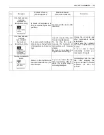
Page 131: ... is on Wait until the glow mark disappears Then get the engine started 2 Default screen normal This screen shows the normal status Hour meter 3 Default screen normal Tachometer numeric This screen shows the normal status Numerical display of tachometer readings 4 AUX port enable switch activated hour meter AUX port enable screen 5 AUX port enable switch activated Tachometer numeric AUX port enable...

Page 132: ...witch 5 to set the clock 2 Tilt up the lock lever This message indicates a procedural step Tilt up the pilot control lock lever This message disappears by tilting up the pilot control lock lever 3 Tilt down the lock lever This message indicates a procedural step Tilt down the pilot control lock lever This message disappears by tilting down the pilot control lock lever 4 Start the engine This messa...

Page 133: ...and insert an unregistered key 10 No more keys can be registered This message appears if the number of registered keys has exceeded their limit No more keys can be registered 11 Press Switch 3 This message appears if the AUX function is tried without pressing the AUX port enable switch Press the AUX port enable switch 12 Not equipped with AUX2 Thumb function The AUX2 port is tried on machines not ...

Page 134: ... engine The engine may get burnt out Immediately stop the engine Immediately contact your local dealer 18 Overvoltage This message appears if a jumper cable is connected to a 24V battery or improper device to get the engine started or if the alternator is in trouble Immediately interrupt the engine if with a 24V battery When the engine gets restarted and is running with no message appearing it mea...

Page 135: ...the normal display is switched back The machine s other functions are operative but an overheat and other problems cannot be detected Immediately contact your local dealer 22 Lock lever system error The lock lever system is in trouble The engine can run but the machine fails to move Immediately contact your local dealer 23 Travel 2 speed system switching The 2 speed switching system is in trouble ...

Page 136: ...in trouble The engine can get restarted and the machine can move but the Thumb 2 system fails When the other systems than the Thumb and AUX port system function the job can be continued Immediately contact your local dealer 30 Periodic check advance notice This message appears 10 hours before the periodic check interval Press the information switch and the list of related components can be reviewe...

Page 137: ...ine with the correct key 35 Registration key unable to start the engine The engine has been started with the red key registration key The engine fails to start Start the engine with the correct key 36 Now HP is limited DPF is regenerated Engine output is limited 37 Exhaust temp rise Operate Carefully Possible to work The exhaust gas temperature rises It is possible to work with careful operation 3...

Page 138: ...Release it Now HP limited Requirement for DPF regeneration DPF must be regenerated but unable to start regeneration because the inhibited switch is activated If you leave the machine with the hydraulic locked the engine can stop automatically Move the machine to a safe place and release the inhibit switch to start DPF regeneration If this error code number still appears immediately contact your lo...

Page 139: ...ill increase sharply Be sure to cool down the engine without stopping it Unclog the oil cooler and other components before using again Check also the hydraulic system for oil leak and other troubles If an oil leak is found immediately contact your local dealer for repair 47 Fuel got mixed with water Water is in the fuel filter and the water separator may be full with water If you don t drain the f...

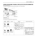
Page 140: ...lay the operator needs preparation of DPF regeneration When the message Now HP is limited appears on the display the DPF is clogged To protect the DPF the engine output is limited When the pilot control lock lever is pulled up the engine will stop after 60 seconds in order to protect DPF When the pilot control lock lever is down the engine will not stop while the engine output is limited Increase ...

Page 141: ...ellow No lighting A Auto regeneration process is locked A The state is before requirement of regeneration A When inhibit switch turns into blinking it requires regeneration Blinking yellow Blinking yellow A Auto regeneration process is locked A Operator needs preparation of DPF regeneration A Move the machine to a safe place and release the inhibit switch A Increase the engine speed over 1650 rpm ...

Page 142: ...ke sure that no people animals plants and flammable materials are within the immediate working area Refer to No 40 in NAVIGATION LIST OF SCREENS section Blinking yellow Blinking red A DPF must be repaired A To protect the DPF engine output is limited A When the pilot control lock lever is raised up the engine will stop after 60 seconds in order to protect DPF A When the Pilot control lock lever is...

Reviews: