background image


ROTEX

®


Operating/Assembly instructions 

Type ZR 

KTR-N 
Sheet: 
Edition: 

40215 EN 
1 of 15 


Please observe protection 

note ISO 16016. 

Drawn: 

2018-08-28 Pz 

Replacing: 

KTR-N dated 2014-03-11 

Verified: 

2018-09-11 Pz 

Replaced by: 


ROTEX

®


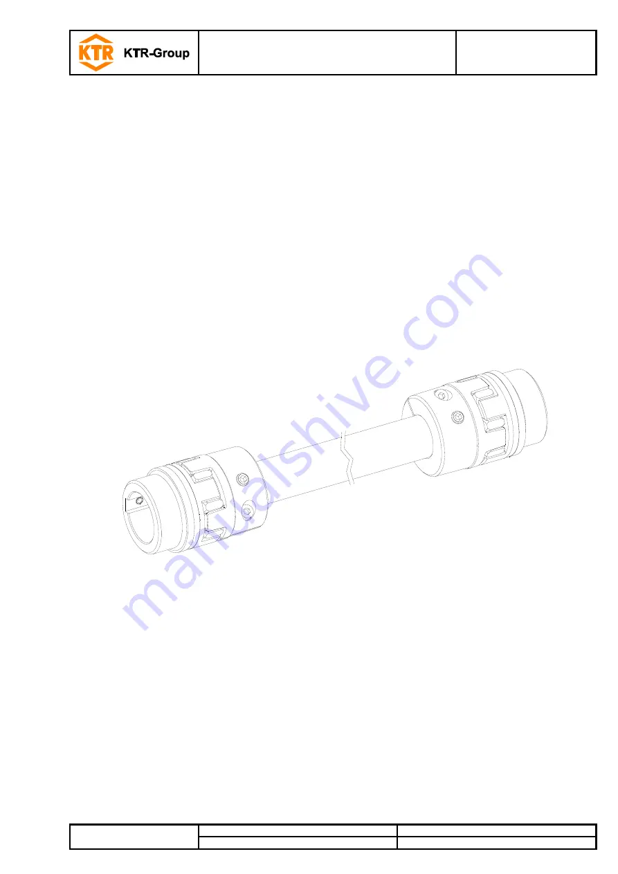
Torsionally flexible jaw couplings type ZR 

and their combinations 


Summary of Contents for ROTEX ZR

Page 1: ...ZR KTR N Sheet Edition 40215 EN 1 of 15 3 Please observe protection note ISO 16016 Drawn 2018 08 28 Pz Replacing KTR N dated 2014 03 11 Verified 2018 09 11 Pz Replaced by ROTEX Torsionally flexible ja...

Page 2: ...ling washer in the cam ground of the hub at the bottom 1 Technical data 3 2 Advice 5 2 1 General advice 5 2 2 Safety and advice symbols 5 2 3 General hazard warnings 5 2 4 Intended use 5 2 5 Coupling...

Page 3: ...48 310 525 655 62 105 85 56 28 3 5 21 50x4 24648 55 410 685 825 74 120 98 65 30 4 0 22 55x4 33544 65 940 1175 80 135 115 75 35 4 5 26 65x5 68329 75 1920 2400 95 160 135 85 40 5 0 30 75x5 108000 Size C...

Page 4: ...80 45 35 5 24 3 0 18 42 265 450 560 55 95 85 50 39 0 26 3 0 20 48 310 525 655 60 105 95 56 45 0 28 3 5 21 55 410 685 825 70 120 110 65 50 0 30 4 0 22 65 940 1175 80 135 115 75 60 0 35 4 5 26 75 1920...

Page 5: ...against accidental switch on You may be seriously hurt by rotating parts Please make absolutely sure to read through and observe the following safety indications All operations on and with the coupli...

Page 6: ...The couplings supplied by KTR should be considered as components not machines or partly completed machines according to EC Machinery Directive 2006 42 EC Consequently KTR does not have to issue a decl...

Page 7: ...r completeness Components of ROTEX type ZR Component Quantity Description 1 2 Hub 2 2 Spider 3 2 ZR clamping hub 4 1 ZR intermediate pipe 5 see table 1 and 2 Cap screws DIN EN ISO 4762 6 1 Setscrews D...

Page 8: ...sequently on unbored or pilot bored as well as finish machined coupling components and spare parts KTR does not assume any warranty claims resulting from insufficient remachining Table 3 Setscrews DIN...

Page 9: ...assembly please make sure that the distance dimension E see table 1 and 2 is observed to allow for axial clearance of the spider when in operation Disregarding this advice may cause damage to the cou...

Page 10: ...the dimension LR2 is achieved see illustration 2 Illustration 6 Illustration 7 Illustration 8 Shift the ZR clamping hub onto the ZR intermediate pipe see illustration 9 Insert the spiders in the cam...

Page 11: ...Please note The displacement figures specified in table 5 are maximum figures which must not arise in parallel If radial and angular displacements arise at the same time the permissible displacement...

Page 12: ...radial displacement Kr mm 1500 rpm 3000 rpm 19 1 2 1 0 0 75 1 Calculate the distance from the center of one spider to the center of the other spider LZK see illustration 1 and 2 LZK LZR 2 x l1 E 2 Cal...

Page 13: ...regularities with the coupling during operation the drive unit must be switched off immediately The cause of the breakdown must be specified by means of the table Breakdowns and if possible be elimina...

Page 14: ...Operating error of the unit 1 Set the unit out of operation 2 Replace complete coupling 3 Inspect alignment 4 Instruct and train the service staff Early wear of spider Misalignment 1 Set the unit out...

Page 15: ...o the condition of the coupling spiders Since the flexible machine bearings of the driving and driven side settle during the course of load please inspect the alignment of the coupling and re align th...

Reviews: