background image

14

WHEELS

103

14.5

Front wheel

14.5.1

Removing the front wheel

Preparatory work

Raise the motorcycle with the lift stand. (

p. 11)

M00116-10

Main work

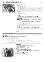
Press the brake caliper onto the brake disc by hand in order to push back the brake
pistons.

Info

Make sure when pushing back the brake pistons that you do not press the
brake caliper against the spokes.

M00117-10

Loosen screw

by several turns.

Release screws

.

Press on screw

to push the wheel spindle out of the axle clamp.

Remove screw

.

M00118-10

Holding the front wheel, withdraw the wheel spindle. Take the front wheel out of
the fork.

Info

Do not pull the hand brake lever when the front wheel is removed.
Always lay the wheel down in such a way that the brake disc is not dam-
aged.

M00119-10

Remove spacers

.

14.5.2

Installing the front wheel

Warning

Danger of accidents

Reduced braking efficiency due to oil or grease on the brake discs.

Always keep the brake discs free of oil and grease, and clean them with brake cleaner when necessary.

M00119-11

Check the wheel bearing for damage and wear.
» If the wheel bearing is damaged or worn:

Change the wheel bearing.

Clean and grease shaft seal rings

and bearing surface

of the spacers.

Long-life grease (

p. 340)

Insert the spacers.

Summary of Contents for 350 EXC-F SIX DAYS EU

Page 1: ...REPAIR MANUAL 2015 350 EXC F EU 350 EXC F SIX DAYS EU 350 EXC F AU 350 EXC F BR 350 EXC F US 350 XCF W US 350 XCF W SIX DAYS US Art no 3206200en ...

Page 2: ......

Page 3: ...y or delete technical specifica tions prices colors forms materials services designs equipment etc without prior notice and without specifying reasons to adapt these to local conditions as well as to stop production of a particular model without prior notice KTM accepts no liability for delivery options deviations from illustrations and descriptions misprints and other errors The models portrayed ...

Page 4: ...Disassembling the hydrostop unit 41 6 13 7 Disassembling the seal ring retainer 41 6 13 8 Checking the fork legs 42 6 13 9 Assembling the seal ring retainer 43 6 13 10 Assembling the hydrostop unit 43 6 13 11 Assembling the piston rod 44 6 13 12 Assembling the cartridge 45 6 13 13 Assembling the fork legs 46 6 13 14 Greasing the steering head bearing 50 6 13 15 Removing the lower triple clamp 50 6...

Page 5: ... the charging voltage 114 15 8 Checking the quiescent current 115 16 BRAKE SYSTEM 116 16 1 Checking the front brake linings 116 16 2 Changing the front brake linings 116 16 3 Checking free travel of hand brake lever 118 16 4 Adjusting the basic position of the hand brake lever All XCF W models 118 16 5 Adjusting free travel of hand brake lever All EXC F models 118 16 6 Checking the brake fluid lev...

Page 6: ...ing the shift mechanism 177 18 4 37 Preassembling the shift shaft 178 18 4 38 Disassembling the main shaft 178 18 4 39 Disassembling the countershaft 179 18 4 40 Checking the transmission 179 18 4 41 Assembling the main shaft 180 18 4 42 Assembling the countershaft 181 18 5 Engine assembly 182 18 5 1 Installing the crankshaft 182 18 5 2 Installing the transmission shafts 183 18 5 3 Installing the ...

Page 7: ... 4 of 8 EXC F EU 240 29 5 Page 5 of 8 EXC F EU 242 29 6 Page 6 of 8 EXC F EU 244 29 7 Page 7 of 8 EXC F EU 246 29 8 Page 8 of 8 EXC F EU 248 29 9 Page 1 of 8 EXC F AU 250 29 10 Page 2 of 8 EXC F AU 252 29 11 Page 3 of 8 EXC F AU 254 29 12 Page 4 of 8 EXC F AU 256 29 13 Page 5 of 8 EXC F AU 258 29 14 Page 6 of 8 EXC F AU 260 29 15 Page 7 of 8 EXC F AU 262 29 16 Page 8 of 8 EXC F AU 264 29 17 Page 1...

Page 8: ...page reference more information is provided on the specified page Indicates information with more details or tips Indicates the result of a testing step Denotes a voltage measurement Denotes a current measurement Denotes a resistance measurement 1 2 Formats used The typographical formats used in this document are explained below Proprietary name Identifies a proprietary name Name Identifies a prot...

Page 9: ... are not taken Warning Identifies a danger that is likely to lead to fatal or serious injury if the appropriate measures are not taken Caution Identifies a danger that may lead to minor injuries if the appropriate measures are not taken Note Identifies a danger that will lead to considerable machine and material damage if the appropriate measures are not taken Warning Identifies a danger that will...

Page 10: ...anger to the environment Do not allow fuel to get into the ground water the ground or the sewage system Use the operating and auxiliary substances such as fuel and lubricants as specified in the manual 3 3 Spare parts accessories Only use spare parts and accessories approved and or recommended by KTM KTM accepts no liability for other products and any resulting damage or loss The current KTM Power...

Page 11: ...AYS XCF W The type label is fixed to the front of the steering head M00233 10 EXC F US The type label is fixed to the front of the steering head The additional type label for Canada is fixed to the front of the front pipe 4 3 Key number All EXC F models 500125 10 EXC F EU AUS BR EXC F SIX DAYS The key number for the steering lock is stamped onto the key connector ...

Page 12: ...in a safe place 4 4 Engine number 401949 10 The engine number is stamped on the left side of the engine under the engine sprocket 4 5 Fork part number 401947 10 The fork part number is stamped on the inner side of the fork stub 4 6 Shock absorber part number 0 0 1 1 401948 10 The shock absorber part number is stamped on the top of the shock absorber above the adjusting ring on the engine side ...

Page 13: ... While riding the side stand must be folded up and secured with the rubber band 5 3 Starting Danger Danger of poisoning Exhaust gases are toxic and inhaling them may result in unconsciousness and or death When running the engine always make sure there is sufficient ventilation and do not start or run the engine in an enclosed space without an effective exhaust extraction system Note Engine failure...

Page 14: ...t in unconsciousness and or death When running the engine always make sure there is sufficient ventilation and do not start or run the engine in an enclosed space without an effective exhaust extraction system Info Press the starter for a maximum of 5 seconds Wait for at least 5 seconds before trying again Shift transmission to neutral EXC F US Turn the key in the ignition lock to the position Tur...

Page 15: ...ncrease damping turn counterclockwise to reduce damping Mount protection caps B01206 10 All SIX DAYS models Turn the white adjusting screw all the way clockwise Info Adjusting screw is located at the upper end of the left fork leg The compression damping is located in the left fork leg COMP white adjusting screw The rebound damping is located in the right fork leg REB red adjusting screw Turn back...

Page 16: ...cated in the left fork leg COMP white adjusting screw Turn back counterclockwise by the number of clicks corresponding to the fork type Guideline Rebound damping Comfort 15 clicks Standard 13 clicks Sport 11 clicks Info Turn clockwise to increase damping turn counterclockwise to reduce damping 6 3 Adjusting the spring preload of the fork EXC F EU AUS BR US XCF W M00092 01 Turn the adjusting screws...

Page 17: ...the brake discs Always keep the brake discs free of oil and grease and clean them with brake cleaner when necessary Clean and oil the dust boots and inner fork tube of both fork legs Universal oil spray p 341 Press the dust boots back into their normal position Remove excess oil M00214 10 EXC F US All XCF W models Push dust boots of both fork legs downward Info The dust boots remove dust and coars...

Page 18: ...ition the fork protector on the right fork leg Mount and tighten the screws Guideline Remaining screws chassis M6 10 Nm 7 4 lbf ft 6 8 Removing the fork legs Preparatory work Remove the headlight mask with the headlight p 98 Raise the motorcycle with the lift stand p 11 Remove the front wheel p 103 M00235 10 Main work Remove screws and take off the clamp Remove the cable binder s Remove screws and...

Page 19: ... Position the fork legs Bleeder screws are positioned toward the front Info Grooves are milled into the side of the upper end of the fork legs The second milled groove from the top must be flush with the top edge of the upper triple clamp M00163 11 Tighten screws Guideline Screw top triple clamp M8 20 Nm 14 8 lbf ft Tighten screws Guideline Screw bottom triple clamp M8 15 Nm 11 1 lbf ft M00137 10 ...

Page 20: ...move the headlight mask with the headlight p 98 Raise the motorcycle with the lift stand p 11 Remove the front wheel p 103 Remove the fork legs p 16 101327 10 Main work Remove screws on the left fork leg Remove the fork protector upwards Remove the screws on the right fork leg Remove the fork protector upwards 6 11 Installing the fork protector 101327 10 Main work Position the fork protector on th...

Page 21: ...cartridge p 26 Assemble the fork legs p 27 6 12 2 Disassembling the fork legs Info The steps are identical for both fork legs Condition The fork legs are disassembled 200736 10 Remove protective cover Note down the present state of rebound damping and compression damping Note down of the present state of the spring preload Completely open the adjusters of the rebound damping and compression dampin...

Page 22: ...10 Push the outer tube downward Pull the spring downward Place the special tool on the hexagonal part Open end wrench T14032 p 353 Info The preload spacers should be above the special tool 200739 10 Clamp the special tool in the bench vise Loosen Preload Adjuster 200740 10 Remove Preload Adjuster with preload spacers Remove adjustment tube 201348 10 Pull the spring downward Remove the special tool...

Page 23: ... out 201350 10 Remove the cartridge 200741 10 Remove dust boot Remove fork protector ring Info The fork protector ring does not necessarily need to be disassembled for the further repair 200742 10 Remove lock ring Info The lock ring has a coarsely finished end against which the screwdriver can be placed 201351 10 Warm up the outer tube in area of the lower sliding bushing Guideline 50 C 122 F Jerk...

Page 24: ...seal ring Take off lock ring Take off dust boot Take out the fork leg 6 12 3 Cartridge disassembly Info The steps are identical for both fork legs Preparatory work Disassemble the fork legs p 19 200746 10 Main work Remove fluid barrier from the piston rod Clamping stand T14016S p 352 200747 10 Remove piston rod from the cartridge 200748 10 Remove washer and spring seat from the cartridge ...

Page 25: ...This step is unnecessary for the further disassembly 200697 10 Degrease the piston rod Clamp the piston rod with the special tool Clamping stand T14016S p 352 200698 10 Remove nut Remove shim stack completely 200699 10 Remove piston Remove shim stack completely 200700 10 Remove spring Remove tap rebound 200701 10 Remove spring Remove valve of the rebound damping together with the spring Take out t...

Page 26: ...n Remove shim stack 200704 10 Remove O ring and seal ring from the compression damping fitting Extract the compression damping fitting 6 12 5 Checking the fork legs Condition The fork legs must be disassembled 200728 10 Check the inner tube and axle clamp for damage If there is damage Change the inner tube 200684 10 Measure the outside diameter at several locations on the inner tube Outside diamet...

Page 27: ...h Guideline Spring length with preload spacer s Weight of rider 65 75 kg 143 165 lb 513 mm 20 2 in Weight of rider 75 85 kg 165 187 lb 513 mm 20 2 in Weight of rider 85 95 kg 187 209 lb 513 mm 20 2 in If the measured value is greater than the specified value Reduce the thickness of the preload spacer If the measured value is less than the specified value Increase the thickness of the preload space...

Page 28: ... locking Extract the compression damping fitting 6 12 7 Assembling the cartridge Info The steps are identical for both fork legs 200715 10 Clamp in the piston rod Clamping stand T14016S p 352 Mount valve of the rebound damping with the spring and O ring Grease the O ring Lubricant T158 p 340 Mount spring 200718 10 Grease tap rebound O ring Lubricant T158 p 340 Mount and tighten the tap rebound Gui...

Page 29: ...ecure the nut by locking 200749 11 Degrease the cartridge and clamp using the special tool Clamping stand T14015S p 352 Mount and tighten screwsleeve Guideline Screwsleeve M29x1 46 Nm 33 9 lbf ft Loctite 241 200748 11 Mount washer and spring seat 200747 11 Push piston rod into the cartridge 200746 11 Screw on fluid barrier to the stop Info The fluid barrier must be screwed on tightly against the s...

Page 30: ... lock ring Grease and slide on seal ring Lubricant T511 p 340 Info The sealing lip should face downward and the open side upward Slide on support ring Remove the special tool 200670 10 Roughen clean and grease the edges of the sliding bushings using 600 grit sand paper Fork oil SAE 4 48601166S1 p 339 200671 10 Slide on lower sliding bushing Mount upper sliding bushing Info Gently pull them apart w...

Page 31: ...spring force The adjustment tube extends more than 7 mm 0 276 in out from the car tridge and cannot be pressed inward against the spring force Screw on water excluder to the stop Info The water excluder must be screwed on tightly against the stop Do not use a tool Mount the special tool on the cartridge Gripping tool T14026S1 p 352 Info The special tool must be used in order that the adjustment tu...

Page 32: ... tool on the hexagonal part Open end wrench T14032 p 353 Remove the special tool Gripping tool T14026S1 p 352 200743 10 Clamp the special tool in the bench vise Grease the thread of the piston rod Lubricant T159 p 340 Grease the upper edge of the piston rod Lubricant T158 p 340 Screw the Preload Adjuster with preload spacer onto the piston rod Info The Preload Adjuster must be screwed in all the w...

Page 33: ... clicks Turn the adjusting screw of spring preload counterclockwise all the way Turn clockwise by the number of turns corresponding to the fork type Guideline Spring preload Preload Adjuster Comfort 1 turn Standard 2 turns Sport 2 turns Alternative 2 Warning Danger of accidents Modifications to the suspension settings can seri ously alter the vehicle s ride behavior Extreme modifications to the ad...

Page 34: ...damage by covering them Do not bend the cables and lines L02471 10 Remove O ring Remove protective ring Take off the lower triple clamp with the steering stem Remove the upper steering head bearing 6 12 11 Installing the lower triple clamp B01605 10 Main work Clean the bearing and sealing elements check for damage and grease High viscosity grease p 340 Insert the lower triple clamp with the steeri...

Page 35: ...BR XCF W Tighten screws Guideline Screw bottom triple clamp M8 15 Nm 11 1 lbf ft M00173 10 EXC F US Tighten screws Guideline Screw bottom triple clamp M8 15 Nm 11 1 lbf ft M00098 10 Tighten screw Guideline Screw top steering head M20x1 5 12 Nm 8 9 lbf ft M00098 11 Tighten screw Guideline Screw top steering stem M8 20 Nm 14 8 lbf ft L02470 11 EXC F EU AUS BR XCF W Tighten screws Guideline Screw top...

Page 36: ...ng play Warning Danger of accidents Unstable vehicle handling from incorrect steering head bearing play Adjust the steering head bearing play without delay Info If the bike is ridden with play in the steering head bearing the bearing and the bearing seats in the frame can become dam aged over time Preparatory work Raise the motorcycle with the lift stand p 11 400738 11 Main work Move the handlebar...

Page 37: ... 14 8 lbf ft Tighten screw Guideline Screw top steering stem M8 20 Nm 14 8 lbf ft M00174 10 EXC F US Loosen screws and Loosen and retighten screw Guideline Screw top steering head M20x1 5 12 Nm 8 9 lbf ft Using a plastic hammer tap lightly on the upper triple clamp to avoid strains Tighten screws Guideline Screw top triple clamp M8 20 Nm 14 8 lbf ft Tighten screw Guideline Screw top steering stem ...

Page 38: ...s p 46 6 13 2 Disassembling the fork legs Info The steps are identical for both fork legs Condition The fork legs are disassembled 201699 10 Note down the current state of rebound damping REB red adjuster of right fork leg Note down the current state of compression damping COMP white adjuster of left fork leg Fully open the adjusters of the rebound and compression damping 201700 10 Clamp the fork ...

Page 39: ...Removing the O ring seat from the cartridge usually requires the application of force 201705 10 Remove dust boot Remove fork protection ring Info The fork protection ring does not necessarily need to be removed for repair work 201706 10 Remove lock ring Info The lock ring has a ground end against which a screwdriver can be posi tioned 201707 10 Warm the outer tube in area of the lower sliding bush...

Page 40: ... fork leg 6 13 3 Removing the spring Info The steps are identical for both fork legs Preparatory work Disassemble the fork legs p 36 201722 11 Main work Pull the spring down Mount the open end wrench on the hexagonal part 201723 10 Clamp the open end wrench in the vise Release screw cap but do not remove it yet Special socket T14047 p 353 201724 11 Pull the spring down Remove the open end wrench R...

Page 41: ...and clamp it in the vise Clamping stand T14049S p 353 Remove adjusting tube Unscrew spring guide 201726 12 Remove spring seat Pull the piston rod out of the cartridge 202481 10 Clamp the tube of the cartridge into a vise Clamping stand T14049S p 353 Release seal ring retainer and remove with the washer 201794 10 Remove lock ring Pull reservoir off of the tube 201795 10 Pull sleeve out of the reser...

Page 42: ...28 10 Main work Degrease the piston rod Clamp the piston rod with the special tool as far up as possible Clamping stand T14049S p 353 Release hydrostop needle and remove it from the piston rod The valve usually remains in the hydrostop needle Info silver hydrostop needle on compression damping side red hydrostop needle on rebound damping side 201729 10 Remove the rebound shim stack Remove piston 2...

Page 43: ...rostop unit on a fitting hexagon socket and clamp into a vice Remove sleeve Remove shim stack 201781 10 Remove adapter Remove hub with washers Info It is possible that only one washer or no washer is present Remove the O ring from the hub 201782 10 Remove shim stack Remove washer Remove O ring 6 13 7 Disassembling the seal ring retainer Info The steps are identical for both fork legs Preparatory w...

Page 44: ... of inner tube 47 975 48 005 mm 1 88878 1 88996 in If the measured value is smaller than the specified value Change the inner tube 200685 10 Measure the run out of the inner tube Inner tube run out 0 20 mm 0 0079 in If the measured value is larger than the specified value Change the inner tube 200632 10 Measure the inside diameter at multiple locations of the outer tube Inside diameter of outer tu...

Page 45: ...s of the preload spacers 6 13 9 Assembling the seal ring retainer Info The steps are identical for both fork legs 201800 10 Mount and grease seal ring Lubricant T158 p 340 Mount and grease O ring Lubricant T158 p 340 Position pilot bushing support 6 13 10 Assembling the hydrostop unit Info The steps are identical for both fork legs 201783 10 Mount and grease O ring Lubricant T158 p 340 Mount washe...

Page 46: ...Add or remove washers 6 13 11 Assembling the piston rod Info The steps are identical for both fork legs except for the hydrostop needle and valve 201790 10 Degrease the piston rod Clamp the piston rod with the special tool Clamping stand T14049S p 353 Lubricate the O ring Mount valve needle in the piston rod Lubricant T158 p 340 201791 10 Mount spring Mount and tighten adapter with spring and wash...

Page 47: ...iston rod M6x0 5 7 Nm 5 2 lbf ft Info silver hydrostop needle on compression damping side red hydrostop needle on rebound damping side Unclamp the piston rod 6 13 12 Assembling the cartridge Info The steps are identical for both fork legs Preparatory work Assemble the seal ring retainer p 43 Assemble the piston rod p 44 201798 10 Main work Mount and grease seal rings and O ring Lubricant T158 p 34...

Page 48: ... the vise Clamping stand T14049S p 353 Screw spring guide all the way on Info The nut must be firmly tightened against the stop by hand Do not use a tool Mount adjusting tube Unclamp the piston rod Mount the preload spacer s 6 13 13 Assembling the fork legs Info When assembling ensure that the right cartridge is mounted in the corresponding inner tube and the right adjuster is mounted on the corre...

Page 49: ... bush ings and lubricate them Fork oil SAE 4 48601166S1 p 339 201716 10 Slide on the lower sliding bushing Mount the upper sliding bushing Info Do not use a tool pull the ends apart slightly by hand 201717 10 Warm the outer tube in area of the lower sliding bushing Guideline 50 C 122 F Slide the outer tube onto the inner tube Hold the lower sliding bushing with the longer section of the special to...

Page 50: ...01719 10 Turn the fork Have the entire filling quantity of fork oil available Oil capacity per fork leg 635 ml 21 47 fl oz Fork oil SAE 4 48601166S1 p 339 Add some of the fork oil while pulling out and pushing in the piston rod numerous times Guideline Fork oil quantity 510 ml 17 24 fl oz 201720 10 Mount and tighten hydrostop unit Guideline Hydrostop unit M30x1 40 Nm 29 5 lbf ft 202091 10 Clamp th...

Page 51: ... needle screw cap with mark REB Compression damping side silver hydrostop needle screw cap with mark COMP 201722 10 Pull the spring down Mount the open end wrench on the hexagonal part Hold the open end wrench Tighten screw cap Guideline Screw cap on piston rod M8x0 75 18 Nm 13 3 lbf ft Special socket T14047 p 353 201701 11 Push the outer tube up Clamp the outer tube in the area of the lower tripl...

Page 52: ...first to get the feel of the new ride behavior Set the adjusters to the positions determined upon removal 6 13 14 Greasing the steering head bearing 800010 10 Remove the lower triple clamp p 50 Install the lower triple clamp p 51 6 13 15 Removing the lower triple clamp Preparatory work Remove the headlight mask with the headlight p 98 Raise the motorcycle with the lift stand p 11 Remove the front ...

Page 53: ...230 10 Position the upper triple clamp with the handlebar Mount screw but do not tighten yet Position the clutch line wiring harness and voltage regulator Mount and tighten screws Guideline Remaining screws chassis M6 10 Nm 7 4 lbf ft B01598 10 Position the fork legs Position bleeder screws toward the front Info The rebound damping is located in the right fork leg REB red adjusting screw The compr...

Page 54: ...ighten screws Finishing work Mount the handlebar cushion Install the front fender p 98 Install the front wheel p 103 Refit the headlight mask with the headlight p 99 Check that the wiring harness throttle cables and brake and clutch lines can move freely and are routed correctly Check the steering head bearing play p 52 Remove the motorcycle from the lift stand p 11 Check the headlight setting p 1...

Page 55: ...le Adjust the play of the steering head bearing p 53 Check the steering head bearing and replace if required Finishing work Remove the motorcycle from the lift stand p 11 6 13 18 Adjusting the play of the steering head bearing Preparatory work Raise the motorcycle with the lift stand p 11 M00140 10 Main work Release screws Remove screw Loosen and retighten screw Guideline Screw top steering head M...

Page 56: ...the handlebar supports Place the handlebar supports in the required position Mount and tighten screws Guideline Screw handlebar holder M10 40 Nm 29 5 lbf ft Loctite 243 Info Position the left and right handlebar supports evenly Position the handlebar Info Make sure the cables and wiring are positioned correctly Position the handlebar clamps Mount and tighten screws evenly Guideline Screw handlebar...

Page 57: ...le cable routing Both throttle cables must be routed to the throttle valve body side by side behind the handlebars and above the fuel tank bearing If the throttle cable is not routed as specified Correct the throttle cable routing Finishing work Install the fuel tank p 90 Mount the seat p 89 7 5 Checking the play in the throttle cable 400192 11 Check the throttle grip for smooth operation Move the...

Page 58: ... play in the throttle cable Preparatory work Remove the seat p 88 Remove the fuel tank p 89 Check the throttle cable routing p 55 M00197 10 Main work Move the handlebar to the straight ahead position Push back sleeves Loosen nut Turn adjusting screw in as far as possible Loosen nut Turn adjusting screw so that there is play in the throttle cable at the throttle grip Guideline Play in throttle cabl...

Page 59: ...a mechanical impact must always be changed Repair of the frame is not authorized by KTM 8 2 Removing the engine guard EXC F AU All SIX DAYS models B01594 10 Turn quick release counterclockwise until it disengages Remove the engine guard 8 3 Installing the engine guard EXC F AU All SIX DAYS models B01595 10 Attach the engine guard on the frame at the rear and swing up at the front Turn quick releas...

Page 60: ...rns Sport 1 25 turns Info Turn clockwise to increase damping turn counterclockwise to reduce damp ing 9 2 Adjusting the low speed compression damping of the shock absorber Caution Danger of accidents Disassembly of pressurized parts can lead to injury The shock absorber is filled with high density nitrogen Adhere to the description provided Info The low speed setting can be seen during the slow to...

Page 61: ...ear wheel sag unloaded Preparatory work Raise the motorcycle with the lift stand p 11 400988 10 Main work Measure the distance as vertically as possible between the rear axle and a fixed point such as a mark on the side cover Make note of the value as measurement Finishing work Remove the motorcycle from the lift stand p 11 9 5 Checking the static sag of the shock absorber 400989 10 Measure distan...

Page 62: ...f pressurized parts can lead to injury The shock absorber is filled with high density nitrogen Adhere to the description provided Info Before changing the spring preload make a note of the present setting e g by measuring the length of the spring Preparatory work Raise the motorcycle with the lift stand p 11 Remove shock absorber p 61 After removing the shock absorber clean it thoroughly 401026 10...

Page 63: ...the shock absorber p 60 Adjust the rebound damping of the shock absorber p 59 9 9 Removing the shock absorber Preparatory work Raise the motorcycle with the lift stand p 11 M00100 10 Main work Remove screw and lower the rear wheel with the swing arm as far as possible without blocking the rear wheel Fix the rear wheel in this position Remove screw push splash protector to the side and remove the s...

Page 64: ...ner p 65 Check the damper p 67 Disassemble the rebound adjuster p 67 Remove the heim joint p 68 Install the heim joint p 69 Assemble the rebound adjuster p 70 Assemble the seal ring retainer p 70 Assemble the piston rod p 71 Assemble the damper p 72 Install the spring p 78 9 12 Removing the spring Condition The shock absorber has been demounted Clamp the shock absorber in a bench vise using soft j...

Page 65: ...adjustment elements of the rebound damping and compres sion damping Remove rubber cap of the reservoir 201616 10 Slowly unscrew screw The pressurized nitrogen is bled off 201617 10 Remove locking cap 201618 10 Press seal ring retainer all the way in with the special tool Disassembly tool T1216 p 351 Remove lock ring Info Do not scratch the inner surface Take out the damper 201619 10 Remove screw D...

Page 66: ... spring p 62 Disassemble the damper p 63 200761 10 Main work Clamp the piston rod with the fork in a bench vise Guideline Use soft jaws Remove nut Info If mount is loosened apply counteractive force Remove rebound damping shim stack Info Guide the rebound damping shim stack onto a screwdriver and put them aside together 200762 10 Remove piston Remove compression damping shim stack Info Guide the c...

Page 67: ...n damping shim stack Info Guide the compression damping shim stack onto a screwdriver and put them aside together 200765 10 Remove rebound damping washer Remove seal ring retainer 200766 10 Remove locking cap and bump rubber 9 15 Disassembling the seal ring retainer Preparatory work Remove the spring p 62 Disassemble the damper p 63 Disassemble the piston rod p 64 200785 10 Main work Remove reboun...

Page 68: ...ot bushing onto the special tool Press drift T1504 p 354 Position the pilot bushing in the seal ring retainer using the special tool Press drift T1504 p 354 Support seal ring retainer with the sleeve of the special tool Press the pilot bushing all the way in Assembly tool T150S p 354 200798 10 Lubricate the special tool Shock absorber fluid SAE 2 5 50180751S1 p 339 Calibration pin T1205 p 350 Supp...

Page 69: ...n rod Diameter 17 95 mm 0 7067 in If the measured value is smaller than the specified value Replace the piston rod Measure the run out of the piston rod Piston rod Run out 0 02 mm 0 0008 in If the measured value is greater than the specified value Replace the piston rod Check the piston rod for damage and wear If there is damage or wear Replace the piston rod 200813 10 Check the piston rings for d...

Page 70: ... heim joint Condition The shock absorber has been demounted 200799 10 Clamp the shock absorber in a vise using soft jaws Remove the collar bushing of the heim joint Pin T120 p 350 Turn the shock absorber around and remove the second heim joint collar bushing 200800 10 Remove seal ring on both sides 200801 10 Press the heim joint against a lock ring using the special tool Pressing tool T1207S p 351...

Page 71: ...ing the heim joint 200803 10 Position new heim joint and special tool Pressing tool T1206 p 350 Press in the heim joint all the way 200801 10 Press the heim joint against the lock ring using the special tool Pressing tool T1207S p 351 Mount the second lock ring 200800 11 Mount seal ring on both sides 200804 10 Position both collar bushings and press in ...

Page 72: ...crew sleeve Guideline Screw sleeve M14x1 18 Nm 13 3 lbf ft Screw out the rebound damping adjusting screw to the stop 200810 10 Grease the O ring of the rebound damping seat Lubricant T159 p 340 Mount and tighten rebound damping valve seat Guideline Rebound damping valve seat M8x1 6 Nm 4 4 lbf ft Loctite 2701 Info The rebound damping valve seat must be pressed inward before tightening 9 22 Assembli...

Page 73: ... with the fork in a bench vise Guideline Use soft jaws Mount bump rubber and locking cap Position the special tool on the piston rod Mounting sleeve T1215 p 351 Grease the dust boot and slide seal ring retainer onto the piston rod Lubricant T625 p 340 Remove the special tool 200767 10 Mount rebound damping washer Mount the compression shim stack with the smaller shims facing downward 200768 10 Gri...

Page 74: ...t sandpaper Clean the piston Mount the piston Guideline View Top view of piston View Bottom view of piston 200772 10 Mount rebound damping shim stack with the smaller shims facing upward Grease the threads of the mount Lubricant T152 p 340 Mount nut but do not tighten it yet 200776 10 Align both pistons using the special tool Centering sleeve T1214 p 351 Tighten the nut Guideline Piston rod nut M1...

Page 75: ... has been assem bled 201619 11 Mount screw but do not tighten yet 201620 10 Grease the O ring of the seal ring retainer Lubricant T158 p 340 Fill the damper cartridge approximately half way Shock absorber fluid SAE 2 5 50180751S1 p 339 Carefully mount the piston rod 201618 11 Mount seal ring retainer and slide it under the ring groove Mount lock ring Info Do not scratch the inner surface Pull out ...

Page 76: ...igh speed Comfort 2 turns Standard 1 5 turns Sport 1 25 turns Turn adjusting screw clockwise up to the last perceptible click Turn counterclockwise by the number of clicks corresponding to the shock absorber type Guideline Rebound damping Comfort 28 clicks Standard 24 clicks Sport 22 clicks Alternative 2 Warning Danger of accidents Modifications to the suspension settings can seri ously alter the ...

Page 77: ...iston rod moves in and out during filling do not immobilize it by hold ing it with your hand 200271 10 Position the control lever as shown in the photo Control lever External tank is set to Closed Damper is set to Vacuum and Oil reservoir is set to Vacuum Activate On Off switch The suction process begins Pressure gauge drops to the required value 0 bar Vacuum gauge drops to the required value 4 mb...

Page 78: ...acuum gauge drops to the required value 8 mbar 200267 10 When the vacuum gauge reaches the required value turn control lever Oil reser voir to Equalize Pressure Guideline 8 mbar The pressure gauge drops to the required value 0 bar 200268 10 When the pressure gauge reaches the required value turn control lever Damper to Pressure Guideline 0 bar Oil is pumped into the damper The pressure gauge incre...

Page 79: ...d tighten screw Guideline Filling port screw M10x1 14 Nm 10 3 lbf ft 9 26 Filling the damper with nitrogen 201616 11 Screw in the screw approx two turns but do not tighten Info The piston rod is completely extended 201628 10 Keep the special tool in place in the bench vise Nitrogen filling tool T170S1 p 354 Connect the special tool to the pressure regulator of the filling cylinder Filling gas nitr...

Page 80: ...7 209 lb 72 N mm 411 lb in Mount intermediate washer and spring retainer Mount ring Alternative 1 Tighten the spring by turning adjusting ring to measurement Guideline Spring preload 8 mm 0 31 in Hook wrench T106S p 349 Alternative 2 Warning Danger of accidents Modifications to the suspension settings can seri ously alter the vehicle s ride behavior Extreme modifications to the adjustment of the s...

Page 81: ...rew and lower the rear wheel with the swingarm as far as possible without blocking the rear wheel Fix the rear wheel in this position Info Raise the wheel slightly to make it easier to remove the screw Swing back the shock absorber G01330 10 Remove spacers on both sides G01331 10 Remove shaft seal rings on both sides G01332 10 Mount special tool Mounting tool heim joint 50329000044 p 342 Press out...

Page 82: ...hock absorber at the swingarm is Teflon coated It must not be greased with grease or with other lubricants Lubricants dis solve the Teflon coating thereby drastically reducing the service life G01330 10 Mount spacers on both sides G01329 10 Position the shock absorber Mount and tighten screw Guideline Screw bottom shock absorber M12 80 Nm 59 lbf ft Loctite 2701 Info Raise the wheel slightly to mak...

Page 83: ...ose the cable Remove screw and take off the manifold 10 2 Installing the manifold G01389 10 Main work Position the manifold and mount springs Spring hooks 50305017000 p 342 G01390 10 Mount and tighten screw Guideline Remaining screws chassis M8 25 Nm 18 4 lbf ft Connect the plug in connector of the lambda sensor Route the cable loosely and secure with a cable binder Finishing work Install the main...

Page 84: ...t screws but do not tighten yet Reconnect spring Tighten screws Guideline Remaining screws chassis M6 10 Nm 7 4 lbf ft 10 5 Changing the glass fiber yarn filling of the main silencer Warning Danger of burns The exhaust system gets very hot when the vehicle is driven Allow the exhaust system to cool down Do not touch hot components Info Over time the fibers of the glass fiber yarn escape and the da...

Page 85: ...ount the new insulating pad on insert and secure it with adhesive tape Slide insert with insulating pad into the main silencer and secure with screws Mount O ring onto connecting cap Slide the new glass fiber yarn filling over the perforated pipe Mount connecting cap and glass fiber yarn filling in the main silencer Info Slide the glass fiber yarn filling into the main silencer with a blunt tool M...

Page 86: ...the eyes and mucuous membranes Wear suitable breathing and eye protection when cleaning the main silencer and carbon screen Clean the main silencer housing and screen of the spark arrestor with compressed air Mount a new O ring on silencer cap Position silencer cap Mount and tighten screws Finishing work Install the main silencer p 82 ...

Page 87: ...toward the front 11 2 Installing the air filter box lid L02467 11 EXC F EU AUS BR EXC F SIX DAYS XCF W Insert the air filter box lid into rear area and clip it into front area M00178 11 EXC F US Insert the air filter box lid into rear area and clip it into front area 11 3 Sealing the air filter box Preparatory work Remove the air filter box lid p 85 401527 10 Main work Seal the air filter box in t...

Page 88: ...e air filter support 11 5 Installing the air filter L00943 10 Main work Mount the clean air filter on the air filter support Grease the air filter in area Long life grease p 340 L02468 11 Insert both parts together position them and fasten them using air filter holder The arrow of marking UP faces up Info If the air filter is not correctly mounted dust and dirt can enter the engine and cause damag...

Page 89: ... Air filter cleaner p 340 Info Only press the air filter to dry it never wring it out Oil the dry air filter with a high quality filter oil Oil for foam air filter p 341 Clean the air filter box Check the intake flange for damage and firm seating Finishing work Install the air filter p 86 Install the air filter box lid p 85 ...

Page 90: ...mmediately and contact a physician Immediately clean contaminated areas on the skin with soap and water If fuel is swallowed contact a physician immediately Change clothing that is contaminated with fuel Store fuel properly in a suitable canister and keep away from children Warning Environmental hazard Improper handling of fuel is a danger to the environment Do not allow fuel to get into the groun...

Page 91: ...occurs with the eyes rinse with water immediately and contact a physician Immediately clean contaminated areas on the skin with soap and water If fuel is swallowed contact a physician immediately Change clothing that is contaminated with fuel Store fuel properly in a suitable canister and keep away from children Preparatory work Remove the seat p 88 M00179 10 Main work Detach connector of the fuel...

Page 92: ... off of the sides of the radiator bracket and lift off the fuel tank M00207 10 EXC F US All XCF W models Pull both spoilers off of the sides of the radiator bracket and lift off the fuel tank 12 6 Installing the fuel tank Danger Fire hazard Fuel is highly flammable Never refuel the vehicle near open flames or burning cigarettes and always switch off the engine first Be careful that no fuel is spil...

Page 93: ...gs and horn and mount and tighten screws Guideline Remaining screws chassis M6 10 Nm 7 4 lbf ft Connect the connector of the horn M00181 11 EXC F US All XCF W models Position the collar bushings and horn and mount and tighten screws Guideline Remaining screws chassis M6 10 Nm 7 4 lbf ft Connect the connector of the horn B01533 10 EXC F EU AUS BR EXC F SIX DAYS XCF W Plug in connector of the fuel p...

Page 94: ...he skin with soap and water If fuel is swallowed contact a physician immediately Change clothing that is contaminated with fuel Warning Environmental hazard Improper handling of fuel is a danger to the environment Do not allow fuel to get into the ground water the ground or the sewage system L02461 10 EXC F EU AUS BR EXC F SIX DAYS XCF W Clean the plug in connection of the fuel line thoroughly wit...

Page 95: ...cigarettes and always switch off the engine first Be careful that no fuel is spilt especially on hot vehicle components Clean up spilt fuel immediately The fuel in the fuel tank expands when warm and may emerge if overfilled Follow the instructions on refueling Warning Danger of poisoning Fuel is poisonous and a health hazard Fuel must not come into contact with the skin eyes or clothing Do not br...

Page 96: ...een Mount the fuel pump housing 305316 10 Mount fuel filter Arrow points away from the fuel pump Mount hose clamps Hose clamp pliers 60029057000 p 345 305313 10 Position the fuel pump Mount fuel connection with the gasket but do not tighten yet Guideline Fuel connection on fuel pump M8 10 Nm 7 4 lbf ft Mount and tighten nut with the gasket Guideline Nut fuel pump fixation M12 15 Nm 11 1 lbf ft ...

Page 97: ... is poisonous and a health hazard Fuel must not come into contact with the skin eyes or clothing Do not breathe in the fuel vapors If contact occurs with the eyes rinse with water immediately and contact a physician Immediately clean contaminated areas on the skin with soap and water If fuel is swallowed contact a physician immediately Change clothing that is contaminated with fuel Store fuel prop...

Page 98: ...f overfilled Follow the instructions on refueling Warning Danger of poisoning Fuel is poisonous and a health hazard Fuel must not come into contact with the skin eyes or clothing Do not breathe in the fuel vapors If contact occurs with the eyes rinse with water immediately and contact a physician Immediately clean contaminated areas on the skin with soap and water If fuel is swallowed contact a ph...

Page 99: ...test 3 min 400927 01 Check the fuel pressure with the filler cap closed Fuel pressure When the fuel pump is active 3 35 3 65 bar 48 6 52 9 psi If the specification is not reached Open the filler cap p 88 Check the tank air vent system 400928 01 Check the fuel pressure with the filler cap open Fuel pressure When the fuel pump is active 3 35 3 65 bar 48 6 52 9 psi If the specification is not reached...

Page 100: ...ighten screws Guideline Remaining screws chassis M6 10 Nm 7 4 lbf ft B01603 11 Mount and tighten screws Guideline Remaining screws chassis M6 10 Nm 7 4 lbf ft Finishing work Refit the headlight mask with the headlight p 99 Check the headlight setting p 127 13 3 Removing headlight mask with headlight M00143 10 EXC F EU AUS BR EXC F SIX DAYS XCF W Switch off all electrical equipment Remove screw and...

Page 101: ...electrical plug in connector and take off the headlight mask with the headlight 13 4 Refitting the headlight mask with the headlight M00127 11 Main work EXC F EU AUS BR EXC F SIX DAYS XCF W Connect the electrical plug in connector M00143 11 Position the headlight mask and fix it with rubber straps Info Ensure the holding lugs engage in the fender Position the brake line and wiring harness Put the ...

Page 102: ...n the headlight mask and fix it with rubber straps Info Ensure the holding lugs engage in the fender Position the brake line and wiring harness Put the clamp on and mount and tighten screw Finishing work Check the headlight setting p 127 ...

Page 103: ... the handling characteristics of the motorcycle The tires mounted on the front and rear wheels must have a similar profile Worn tires have a negative effect on handling characteristics especially on wet surfaces 400602 10 Check the front and rear tires for cuts run in objects and other damage If the tire exhibits cuts run in objects or other damage Change the tire Check the depth of the tread Info...

Page 104: ...rake disc 14 4 Checking spoke tension Warning Danger of accidents Instable handling due to incorrect spoke tension Ensure that the spoke tension is correct Info A loose spoke can cause wheel imbalance which leads to more loose spokes in a short time If the spokes are too tight they can break due to local overload Check the spoke tension regularly especially on a new motorcycle 400694 01 Tap each s...

Page 105: ...ront wheel withdraw the wheel spindle Take the front wheel out of the fork Info Do not pull the hand brake lever when the front wheel is removed Always lay the wheel down in such a way that the brake disc is not dam aged M00119 10 Remove spacers 14 5 2 Installing the front wheel Warning Danger of accidents Reduced braking efficiency due to oil or grease on the brake discs Always keep the brake dis...

Page 106: ...ully tighten screw Guideline Screw fork stub M8 15 Nm 11 1 lbf ft 14 5 3 Removing the front brake disc Preparatory work Raise the motorcycle with the lift stand p 11 Remove the front wheel p 103 G01387 10 Main work Remove screws Take off the brake disc 14 5 4 Installing the front brake disc G01387 10 Main work Clean the contact surface of the brake disc Position the brake disc with the label facin...

Page 107: ...of the swingarm Info Do not operate the foot brake when the rear wheel is removed Always lay the wheel down in such a way that the brake disc is not dam aged M00124 10 Remove spacers 14 6 2 Installing the rear wheel Warning Danger of accidents Reduced braking efficiency due to oil or grease on the brake discs Always keep the brake discs free of oil and grease and clean them with brake cleaner when...

Page 108: ...l the brake linings are in contact with the brake disc and there is a pressure point Finishing work Remove the motorcycle from the lift stand p 11 14 6 3 Removing the rear brake disc Preparatory work Raise the motorcycle with the lift stand p 11 Remove the rear wheel p 104 G01388 10 Main work Remove screws Take off the brake disc 14 6 4 Installing the rear brake disc G01388 10 Main work Clean the ...

Page 109: ...st be possible to pull up the chain at least to the point where it makes contact with chain guard Chain wear is not always even so you should repeat this measurement at different chain positions Chain tension 55 58 mm 2 17 2 28 in If the chain tension does not meet specifications Adjust the chain tension p 107 Finishing work Remove the motorcycle from the lift stand p 11 14 6 6 Adjusting the chain...

Page 110: ...6 7 Checking the chain rear sprocket engine sprocket and chain guide Preparatory work Raise the motorcycle with the lift stand p 11 400227 01 Main work Shift gear to neutral Check the rear sprocket and engine sprocket for wear If the rear sprocket or engine sprocket is worn Change the power set Info The engine sprocket rear sprocket and chain should always be replaced together 400987 10 Pull on th...

Page 111: ... or below the chain sliding piece Change the chain sliding piece Check that the chain sliding piece is firmly seated If the chain sliding piece is loose Tighten the chain sliding piece Guideline Screw chain sliding piece M8 15 Nm 11 1 lbf ft 401760 01 Check the chain guide for wear Info Wear is visible on the front of the chain guide If the light part of the chain guide is worn Change the chain gu...

Page 112: ...scs Always keep the brake discs free of oil and grease and clean them with brake cleaner when necessary Warning Environmental hazard Hazardous substances cause environmental damage Oil grease filters fuel cleaners brake fluid etc should be disposed of as stipulated in applicable regulations Info The service life of the chain depends largely on its maintenance Preparatory work Raise the motorcycle ...

Page 113: ...es are used Use only fuses with the prescribed amperage Never by pass or repair fuses 400273 10 Main work Insert the main fuse Fuse 75011088010 p 224 Info A reserve fuse is located in the starter relay Replace a burned out fuse only by an equivalent fuse Replace the protection cover Finishing work Install the air filter box lid p 85 15 3 Changing the fuses of individual power consumers Info The fu...

Page 114: ...umer is functioning properly Close the fuse box cover Finishing work Mount the seat p 89 15 4 Removing the battery Warning Risk of injury Battery acid and battery gases cause serious chemical burns Keep batteries out of the reach of children Wear suitable protective clothing and goggles Avoid contact with battery acid and battery gases Keep sparks and open flames away from the battery Only charge ...

Page 115: ... the seat p 89 15 6 Charging the battery Warning Risk of injury Battery acid and battery gases cause serious chemical burns Keep batteries out of the reach of children Wear suitable protective clothing and goggles Avoid contact with battery acid and battery gases Keep sparks and open flames away from the battery Only charge in well ventilated rooms In the event of skin contact rinse with large amo...

Page 116: ...ery charger 58429074000 You can also use the battery charger to test the open circuit voltage and starting voltage of the battery and to test the alternator With this device you cannot over charge the battery Info Never remove lid Charge the battery with a maximum of 10 of the capacity specified on battery housing Switch off the battery charger after charging and disconnect from the battery Guidel...

Page 117: ...ve cable from the battery Measure the current between battery ground and the negative cable Info The value of the quiescent current applies only to vehicles in the original state i e without additional power consumers Maximum closed circuit current 1 0 mA If the measured value is higher than the specified value Disconnect the voltage regulator from the wiring harness and perform the measurement ag...

Page 118: ...e according to the service schedule Warning Danger of accidents Reduced braking efficiency due to oil or grease on the brake discs Always keep the brake discs free of oil and grease and clean them with brake cleaner when necessary Warning Danger of accidents Reduced braking efficiency due to use of non approved brake linings Brake linings available from accessory suppliers are often not tested and...

Page 119: ...ke linings Clean the brake caliper and brake caliper support 100397 01 Check that leaf spring in the brake caliper and sliding plate in the brake caliper support are seated correctly M00112 01 Insert the new brake linings insert the pin and mount the cotter pins Info Always change the brake linings in pairs Operate the hand brake lever repeatedly until the brake linings are in contact with the bra...

Page 120: ...11 Check the free travel of the hand brake lever p 118 Adjust the basic setting of the hand brake lever to your hand size by turning adjust ing screw Info Turn the adjusting screw clockwise to increase the distance between the hand brake lever and the handlebar Turn the adjusting screw counterclockwise to decrease the distance between the hand brake lever and the handlebar The range of adjustment ...

Page 121: ... not continue riding Warning Skin irritation Brake fluid can cause skin irritation on contact Avoid contact with skin and eyes and keep out of the reach of children Wear suitable protective clothing and goggles If brake fluid comes into contact with the eyes flush the eyes thoroughly with water and consult a physician immediately Warning Danger of accidents Reduced braking efficiency due to old br...

Page 122: ...ipulated in applicable regulations Info Avoid contact between brake fluid and painted parts Brake fluid attacks paint Use only clean brake fluid from a sealed container G01391 10 Move the brake fluid reservoir mounted on the handlebar to a horizontal position Cover the painted parts Remove screws Remove cover with membrane Draw the old brake fluid out of the brake fluid reservoir using a syringe a...

Page 123: ...or spilt brake fluid immediately with water Check the hand brake lever for a firm pressure point 16 9 Checking the rear brake linings Warning Danger of accidents Reduced braking efficiency caused by worn brake linings Change worn brake linings immediately M00113 10 Check the brake linings for minimum thickness Minimum thickness 1 mm 0 04 in If the minimum thickness is less than specified Change th...

Page 124: ...ndition at delivery and the warranty is no longer valid Warning Environmental hazard Hazardous substances cause environmental damage Oil grease filters fuel cleaners brake fluid etc should be disposed of as stipulated in applicable regulations Info Never use DOT 5 brake fluid It is silicone based and purple in color Oil seals and brake lines are not designed for DOT 5 brake fluid Avoid contact bet...

Page 125: ... builds up on the rear brake circuit The rear brake can fail due to overheating Adjust the free travel on foot brake lever according to specifications 402026 10 Disconnect spring Move the foot brake lever back and forth between the end stop and the contact to the foot brake cylinder piston and check free travel Guideline Free travel at foot brake lever 3 5 mm 0 12 0 2 in If the free travel does no...

Page 126: ...king or that the brake linings are completely worn down Check the brake system and do not continue riding Warning Danger of accidents Reduced braking efficiency due to old brake fluid Change the brake fluid of the front and rear brake according to the service schedule L02464 10 Stand the vehicle upright Check the brake fluid level in level viewer If the brake fluid level has dropped below marking ...

Page 127: ...nd the vehicle upright Remove screw cap with membrane and the O ring Add brake fluid to level Brake fluid DOT 4 DOT 5 1 p 338 Mount the screw cap with the membrane and the O ring Info Clean up overflowed or spilt brake fluid immediately with water 16 15 Changing the rear brake fluid Warning Skin irritation Brake fluid can cause skin irritation on contact Avoid contact with skin and eyes and keep o...

Page 128: ...29 36 psi G01338 10 Pull off protection cap of the bleeder screw Connect the hose of the bleeder bottle Bleeding device 00029013100 p 342 Open bleeder screw by approx one half turn Info Bleed until new brake fluid emerges from the bleeder bottle hose without bubbles Tighten the bleeder screw Close shut off valve Open the bleeder screw again until no more brake fluid emerges Info This prevents over...

Page 129: ... range p 127 17 2 Adjusting the headlight range Preparatory work Check the headlight setting p 127 L02459 10 Main work EXC F EU AUS BR EXC F SIX DAYS XCF W Loosen screw Adjust the headlight range by pivoting the headlight Guideline The boundary between light and dark must be exactly on the lower mark for a motorcycle with driver instructions on how to apply the mark Checking the headlight setting ...

Page 130: ... the circumference of the 21 front wheel with stan dard tires The display then changes to the last selected mode 17 5 Setting kilometers or miles Info If you change the unit the value ODO is retained and converted accordingly The values TR1 TR2 A1 A2 and S1 are cleared when the unit of measure is changed Condition The motorcycle is stationary 400329 01 Repeatedly press the button briefly until H a...

Page 131: ...briefly until CLK appears at the bottom right of the display Press the button for 2 3 seconds The hour display flashes Set the hour display with the button and or button Wait 3 5 seconds The next segment of the display flashes and can be set You can set the following segments in the same way as the hours by pressing the button and the button Info The seconds can only be set to zero If no button is...

Page 132: ...Main work Repeatedly press the button briefly until H appears at the bottom right of the display Press the button for 2 3 seconds When WS flashes press the button briefly Info The wheel circumference is displayed in millimeters Enlarging the wheel circumference Press the button Reducing the wheel circumference Press the button Info If no button is pressed for 20 seconds or if no impulse comes from...

Page 133: ...riefly press the button LAP 1 appears on the left side of the display The laps 1 10 can be viewed with the button Press and hold the button for 3 5 seconds to clear the lap times Briefly press the button Next display mode Info When a signal from the wheel speed sensor arrives the left side of the dis play changes back to the SPEED mode ...

Page 134: ...er p 82 Remove the seat p 88 Remove the fuel tank p 89 308474 10 Main work Remove screw Disconnect the negative cable from the battery G01425 10 Remove screws with washers Remove the cable binder s Take off the frame protector on both sides Info Pay attention to the holding lugs G01427 10 Loosen hose clip G01428 10 Slide back cover Unplug connector ...

Page 135: ... off the vent hose G01430 10 Remove screw Loosen screw Repeat the operation on the opposite side G01431 10 Swing up the subframe and secure it G01432 10 Remove screw Swing back the shock absorber G01433 10 Remove springs Spring hooks 50305017000 p 342 ...

Page 136: ...le Remove screw Remove the manifold G01435 10 Slide back cover Remove nut Detach the cable G01436 10 Loosen hose clip Take off the radiator hose G01437 10 Disconnect spring G01438 10 Remove screw Remove screw Take off the engine sprocket cover G01439 10 Remove the connecting link of the chain Take off the chain ...

Page 137: ...01441 10 Disconnect plug in connector Disconnect plug in connector Slide back cover Unplug connector Pull of the spark plug connector G01442 10 Loosen hose clip Pull off the throttle valve body from the rear G01443 10 Loosen hose clip Take off the radiator hose G01444 10 Remove screw connections Remove the engine braces G01445 10 Remove nut Remove the swingarm pivot Pull the swingarm slightly towa...

Page 138: ...the engine G01447 10 Main work Position the engine in the frame G01446 11 Mount screws but do not tighten yet Guideline Engine attachment bolt M10 60 Nm 44 3 lbf ft G01445 11 Position the swingarm Mount the swingarm pivot Mount nut but do not tighten it yet Guideline Nut swingarm pivot M16x1 5 100 Nm 73 8 lbf ft G01444 11 Position the engine braces Mount and tighten screw caps Guideline Screw engi...

Page 139: ...t the throttle valve body Position and tighten hose clip G01441 11 Plug in connector Position the cover Connect plug in connector Connect plug in connector Mount the spark plug connector G01440 11 Position the clutch slave cylinder with the gasket Mount and tighten screws Guideline Screw clutch slave cylinder M6 10 Nm 7 4 lbf ft G01439 11 Mount the chain Connect the chain with connecting link ...

Page 140: ...bf ft G01437 11 Mount spring G01436 11 Mount the radiator hose Position and tighten hose clip G01435 11 Position the cable Mount and tighten nut Position the cover G01433 11 Position the manifold and mount springs Spring hooks 50305017000 p 342 G01434 11 Mount and tighten screw Guideline Remaining screws chassis M8 25 Nm 18 4 lbf ft Route the lambda sensor cable and secure it with a cable binder P...

Page 141: ...me Info Watch out for the intake flange Mount and tighten screw Guideline Screw subframe M8 35 Nm 25 8 lbf ft Loctite 2701 Remove screw Mount and tighten screw Guideline Screw subframe M8 35 Nm 25 8 lbf ft Loctite 2701 Repeat the operation on the opposite side G01429 11 Mount the vent hose Position hose clamp G01428 11 Plug in connector Position the cover G01427 11 Position and tighten hose clip ...

Page 142: ...he seat p 89 G01531 10 Remove screw cap on the clutch cover and fill in engine oil Engine oil 1 2 l 1 3 qt Engine oil SAE 10W 50 p 338 Alternative engine oil for harsh oper ating conditions and increased per formance Engine oil SAE 10W 60 00062010035 p 338 Mount and tighten fitting Danger Danger of poisoning Exhaust gases are toxic and inhaling them may result in unconsciousness and or death When ...

Page 143: ...ount the special tool on the engine mounting block Engine fixing arm 77229002000 p 346 Engine assembly stand 61229001000 p 345 Mount the engine on the special tool Info Work with an assistant or a motorized hoist 18 3 2 Removing the clutch push rod 308567 10 Remove clutch push rod 18 3 3 Removing the spacer 308568 10 Remove spacer of the countershaft Remove O ring 18 3 4 Draining the engine oil 30...

Page 144: ... the oil filter cover with the O ring 308573 10 Pull oil filter out of the oil filter housing Circlip pliers reverse 51012011000 p 343 18 3 6 Removing the spark plug 308574 10 Remove the spark plug using special tool Spark plug wrench 77229072000 p 349 18 3 7 Removing the valve cover 308575 10 Remove screws Remove the valve cover with the valve cover seal ...

Page 145: ... kick starter 308577 10 Remove screw with the washer Take off the kick starter 308578 10 Remove distance sleeve 18 3 9 Removing the alternator cover 308579 10 Remove screws Remove the alternator cover 308580 10 Take off the alternator cover gasket Dowels remain in the engine case ...

Page 146: ...gs on the cylinder head are located flush above the flat areas of the camshafts 308583 10 Remove screw with the washer Info Check through the hole whether the position notch of the crankshaft is visi ble Mount and tighten screw without the washer 18 3 12 Removing the timing chain tensioner 308584 10 Loosen screw Remove screw with the seal ring G00447 10 Pull out timing chain tensioner Remove O rin...

Page 147: ...il Take off the camshaft bearing bridge 308595 10 Take the timing chain off the camshaft gear Remove the camshafts 18 3 14 Removing the cylinder head 308596 10 Remove nut with the washer 308597 10 Loosen nuts in a crisscross pattern and remove them with the washers Remove the cylinder head 308598 10 Remove cylinder head gasket ...

Page 148: ...be performed on the cylinder and piston the piston can remain in the cylinder 308600 10 Take off cylinder base gasket 18 3 16 Removing the starter drive 308604 10 Remove screw 308605 10 Insert special tool in the crankshaft Protection cover 75029090000 p 346 Attach special tool to the rotor Hold the special tool and pull off the rotor by turning in the screw Extractor 58012009000 p 343 Info Ensure...

Page 149: ...ar 308608 10 Remove screws Remove the inside alternator cover 308609 10 Take off gasket 308610 10 Remove screws Take off the starter motor 18 3 17 Removing the suction pump 308612 10 Remove screws Take off oil pump cover 308613 10 Remove O ring ...

Page 150: ...ller 18 3 18 Removing the water pump wheel 308616 10 Remove screws Take off the water pump cover 308617 10 Remove nut Take off the two part water pump impeller 18 3 19 Removing the clutch cover 308618 10 Remove screws Take off the clutch cover Remove the clutch cover seal ...

Page 151: ... clutch discs 308619 10 Remove screws Take off spring retainer 308620 10 Take off spring washer 308621 10 Take off pretension ring 308622 10 Take off pressure cap 308623 10 Completely remove clutch disc pack Remove clutch pressure piece ...

Page 152: ...The washer usually sticks to the inner clutch hub Take off clutch basket 308626 10 Take off needle bearing and collar sleeve 18 3 22 Removing the intermediate kick starter gear 308630 10 Detach kick starter spring Turn kick starter shaft counterclockwise and pull it out Info The stop disk of the kick starter shaft usually sticks to the bearing 18 3 23 Removing the intermediate kick starter gear 30...

Page 153: ...locking lever from shift drum locating unit and remove the shift drum locating unit Relieve tension from the locking lever 18 3 26 Removing the locking lever 308634 10 Unscrew and remove together with locking lever washer sleeve and spring 18 3 27 Removing the force pump 308637 10 Remove lock ring Take off washer Take off oil pump idler gear with the washer 308638 10 Remove lock ring Take off wash...

Page 154: ... Removing the primary gear 308641 10 Remove nut Info Left handed thread Take off primary gear 18 3 29 Removing the timing chain 308642 10 Remove screws Remove the timing chain tensioning rail Remove the timing chain guide rail 308643 10 Remove screw Take off balancer shaft with the timing chain and timing chain securing guide Info If the timing chain is going to be used again mark its direction of...

Page 155: ...ool into the crankshaft Protection cover 75029090000 p 346 Mount special tool with the appropriate screws Puller 77229048000 p 348 Info Use the drill hole marked with 772 Take off the section of the engine case Info Do not subject the section of the engine case to any stress The washer of the main shaft usually adheres to the bearing Take off the left section of the engine case Remove the dowels R...

Page 156: ...1 10 Tilt shift forks to the side Info Do not misplace the shift rollers Remove shift drum 18 3 34 Removing the shift forks 308652 10 Remove shift forks Info Do not misplace shift rollers 18 3 35 Removing the transmission shafts 308654 10 Remove lock ring 308655 10 Pull both transmission shafts out of the bearing seats together ...

Page 157: ...sing a suitable tool 308660 10 Blow out oil nozzle with compressed air and check that it is clear Guideline Oil nozzle for balancer shaft lubrication M4 2 Nm 1 5 lbf ft Loctite 243 Insert the new cold bearings into the bearing seats of the hot engine case section and if necessary use a suitable press drift to push the bearing all the way to the stop or so that it is flush Info When pressing the be...

Page 158: ...ubrication Remove oil nozzle for piston cooling Remove screws Remove the bearing retainers Remove any sealing mass remnants and clean the engine case section thoroughly Warm the engine case section in an oven Guideline 150 C 302 F Knock the engine case section against a level wooden plate This will cause the bearings to drop out of the bearing seats Info Any bearings that remain in the engine case...

Page 159: ...eal ring of the countershaft so it is flush with the open side fac ing in Mount and tighten oil nozzle Guideline Oil nozzle for clutch lubri cation M5 6 Nm 4 4 lbf ft Loctite 243 Mount and tighten oil nozzle Guideline Oil nozzle piston cooling M5 2 Nm 1 5 lbf ft Loctite 243 Position all bearing locks Mount and tighten screws Guideline Locking screw for bearing M5 6 Nm 4 4 lbf ft Loctite 243 400996...

Page 160: ... Press the new bearing all the way in from the inside to the outside using a suit able tool 302692 10 Press in shaft seal ring all the way with the open side facing outward 308680 10 Remove lock ring 308681 10 Remove shaft seal ring of the crankshaft Press the new shaft seal ring all the way in with the open side facing outward Info Provide suitable support for the clutch cover while pressing in ...

Page 161: ...spring length of the oil pressure regulator valve Oil pressure regulator valve Minimum length of pressure spring 23 5 mm 0 925 in If the measured value does not meet specifications Change the spring Check ball and the sealing seat If there is damage or wear Change the ball and machine the sealing seat 305033 10 Install ball and pressure spring Mount and tighten screw plug with sealing washer Guide...

Page 162: ...8661 10 Fix the crankshaft in the vise Info Use soft jaws Warm up special tool Guideline 150 C 302 F Tool for inner bearing race 58429037037 p 344 Push the warmed up special tool onto the crankshaft bearing inner race press firmly together and pull jointly from the crankshaft Take off the compensating disk Repeat the operation on the opposite side 18 4 7 Installing the crankshaft bearing inner rac...

Page 163: ... p 346 Info Hold the lower crank web Remove the connecting rod and bearing 302918 10 Press the crank pin out of the lower crank web 302912 10 Press in the new crank pin as far as possible Oil hole is aligned with oil hole If the oil holes are not correctly aligned the conrod bearing will not be sup plied with oil Blow compressed air through the oil channel to check that it is clear 306572 10 Mount...

Page 164: ...haft slowly Check the crankshaft run out on both bearing pins Crankshaft run out at bearing pin 0 03 mm 0 0012 in If the crankshaft run out at the bearing pin is larger than the specification Align the crankshaft 18 4 10 Measuring the crankshaft end play 306528 10 Insert the crankshaft into the right section of the engine case Info Do not forget the fitted bushings Mount the left section of the en...

Page 165: ...e developed by Mahle The name is derived from the two materials used in this procedure a layer of nickel into which is embedded the particularly hard silicone carbide The most important advantages of the Nikasil coating are very good heat conductivity resulting in much improved performance low wear and a lightweight cylinder 18 4 14 Checking measuring the cylinder 302700 10 Check the cylinder bear...

Page 166: ...iston and if necessary the cylinder Check that the piston rings move easily in the piston ring grooves If the piston ring is stiff Clean the piston ring groove Tip An old piston ring can be used to clean the piston ring groove Check the piston rings for damage If the piston ring is damaged Replace the piston ring Info Mount the piston ring with the marking facing upward Check the piston pins for d...

Page 167: ...nd align with the piston Guideline Below the upper edge of the cylinder 20 mm 0 79 in Measure the end gap with feeler gauge Guideline Piston ring end gap Compression ring 0 40 mm 0 0157 in Oil scraper ring 0 80 mm 0 0315 in If the end gap is greater than the specified measurement Check measure the cylinder p 163 If cylinder wear lies within the specified tolerance Change the piston ring Mount the ...

Page 168: ...aring to the camshaft gear Pull lever away from camshaft and release it If the lever does not return to its original position Change the exhaust camshaft 18 4 20 Checking the pivot points of the camshafts 308668 10 Check the pivot points of the camshafts If there is damage or wear Change the cylinder head with the camshaft bearing bridge 308669 10 Position the camshafts The valves are not activate...

Page 169: ... the cam lever shaft Hold cam levers and remove the cam lever shaft Info If the cam levers will continue to be used note down their installation posi tion Take the shims out of the valve spring retainers and lay them to one side according to their normal built in position 302711 10 Pre tension the valve spring using the special tool Valve spring compressor 59029019000 p 344 Insert for valve spring...

Page 170: ...eat or deviates from the specifi cation Rework the valve seat 18 4 23 Checking the valve springs 305015 10 Check the valve springs for breakage and wear visual check If the valve spring is broken or worn Change the valve spring Measure the length of the valve springs Valve spring Minimum length 42 00 mm 1 6535 in If the measured value does not meet specifications Change the valve springs 18 4 24 C...

Page 171: ... and the special tool check the sealing area of the cylinder for distortion Feeler gauge 59029041100 p 344 Cylinder cylinder head distortion of sealing area 0 10 mm 0 0039 in If the measured value does not meet specifications Change the cylinder head 302808 10 Check sealing seat of the valves Valve sealing seat width Intake 1 40 mm 0 0551 in Valve sealing seat width Exhaust 1 40 mm 0 0551 in If th...

Page 172: ...tion cam levers in the positions they had before they were removed Mount the cam lever shafts Remove screw Mount and tighten screw plugs Guideline Screw plug cam lever axis M10x1 10 Nm 7 4 lbf ft Place shims into the valve spring retainers according to the installation position 18 4 28 Checking the freewheel 302804 10 Insert freewheel gear into the freewheel hub turning the freewheel gear clock wi...

Page 173: ...Press expansion ring together with suitable pliers and take off 308676 10 Take freewheel out of the primary gear 18 4 30 Installing the freewheel 308676 11 Thoroughly oil all parts Slide freewheel into the primary gear Info Note the direction of rotation 308677 10 Mount spreader ring ...

Page 174: ... in groove of the primary gear 308674 11 Mount lock ring 18 4 31 Preassembling the kick starter shaft 301000 10 Mount washer and needle bearing 301001 10 Mount starter wheel Mount washer and lock ring 301002 10 Mount kick starter ratchet wheel Marking points to drill hole 301003 10 Position spring and mount washer ...

Page 175: ...the starter idler gear Check the gear mesh and bearing of torque limiter for damage and wear If there is damage or wear Change the torque limiter Check the gear mesh and bearing of freewheel gear for damage and wear If there is damage or wear Change the freewheel gear or bearing Check freewheel for damage and wear If there is damage or wear Change the free wheel Check the gear mesh of starter moto...

Page 176: ...in tensioning rail for damage and wear If there is damage or wear Replace the timing chain tensioning rail Check the timing chain guide rail for damage and wear If there is damage or wear Replace the timing chain guide rail Check the timing chain securing guide for damage and wear If there is damage or wear Replace the timing chain securing guide Check camshaft gears for damage and wear If there i...

Page 177: ...ent mechanism engages and the piston remains in place Final position of the piston after engagement 3 mm 0 12 in Info This position is necessary for installation If the timing chain tensioner is now pressed again and is only extended a maximum of half way it is prevented from extending completely This locks the detent mechanism and the timing chain tensioner can no longer be squeezed together This...

Page 178: ...e is damage or wear Change the inner clutch hub Check the contact surfaces of the clutch facing disks in clutch basket for damage and wear If there is damage or wear Change the clutch lining discs and the clutch basket Check needle bearing and collar sleeve for damage and wear If there is damage or wear Change the needle bearing and collar sleeve Check the intermediate disc for damage and wear If ...

Page 179: ...g Check the shift rollers for damage and wear If there is damage or wear Change the shift rollers Check the springs of shift rails for damage and wear If the spring is damaged or worn Change the spring of the shift rail Check the shift rails for run out on a flat surface If there is run out Change the shift rail Check the shift rails for scoring wear and smooth operation in the shift forks If scor...

Page 180: ...ne Use soft jaws Mount sliding plate with the guide pin facing downward and put the guide pin on the shift quadrant Mount pressure spring Slide on spring guide push return spring with the offset end facing upward over the spring guide and lift the offset end over abutment bolt Mount washer 18 4 38 Disassembling the main shaft 305011 10 Secure the main shaft with the toothed end facing downward in ...

Page 181: ...dler gear Remove needle bearing Remove stop disk Remove 6th gear sliding gear Remove stop disk Remove lock ring Remove 3rd gear idler gear Remove needle bearing Remove 4th gear idler gear Remove needle bearing Remove stop disk and lock ring Remove 5th gear sliding gear Remove lock ring Remove stop disk Remove the 2nd gear idler gear Remove needle bearing 18 4 40 Checking the transmission Condition...

Page 182: ... damage or wear Change the gear wheel pair Check the tooth faces of idler gears sliding gears and fixed gear for damage and wear If there is damage or wear Change the gear wheel pair Check the tooth profiles of sliding gears for damage and wear If there is damage or wear Change the gear wheel pair Check sliding gears for smooth operation in the profile of main shaft If the sliding gear does not mo...

Page 183: ...r idler gear Mount stop disk and lock ring Mount 3rd 4th gear sliding gear with the small gear wheel facing downward Mount lock ring Mount stop disk Mount needle bearing Mount 5th gear idler gear Mount 2nd gear fixed gear and stop disk Finally check all gear wheels for smooth operation 18 4 42 Assembling the countershaft Info Use new lock rings with every repair Preparatory work Carefully lubricat...

Page 184: ... Mount 4th gear idler gear Mount needle bearing Mount 3rd gear idler gear Mount lock ring and stop disk Mount 6th gear sliding gear with the shift groove facing downward Mount stop disk Mount needle bearing Mount 1st gear idler gear Mount stop disk Finally check all gear wheels for smooth operation 18 5 Engine assembly 18 5 1 Installing the crankshaft 308656 10 Position the right section of the en...

Page 185: ... smaller inside diameter mount this in the shift groove of the main shaft Mount shift fork in the lower shift groove of the countershaft Mount shift fork in the upper shift groove of the countershaft Slide on shift rollers Tip Fix the shift rollers in the shift forks with grease 18 5 4 Installing the shift drum 308651 11 Push shift drum into the bearing seat Put shift forks in the shift drum Info ...

Page 186: ...ction of the engine case If necessary strike it lightly with a rub ber mallet and turn the transmission shafts Info Do not use the screws to pull the two sections of the engine case together Mount screws but do not tighten yet Guideline Screw engine case M6x55 10 Nm 7 4 lbf ft Mount screws but do not tighten them yet Guideline Screw engine case M6x65 10 Nm 7 4 lbf ft Mount screws but do not tighte...

Page 187: ...Loctite 243 308642 11 Position timing chain guide rail Mount and tighten screw Guideline Screw timing chain guide rail M6 10 Nm 7 4 lbf ft Loctite 243 Position timing chain tensioning rail Mount and tighten screw Guideline Screw timing chain ten sioning rail M8 15 Nm 11 1 lbf ft Loctite 243 18 5 9 Installing the primary gear 308645 10 Position primary gear The wide tooth of the primary gear engage...

Page 188: ...ount pin 308639 11 Position the oil pump cover Marking faces upward Mount and tighten screws Guideline Screw oil pump cover M5 6 Nm 4 4 lbf ft Loctite 243 Insert pin 308638 11 Position oil pump gear wheel Mount washer Mount lock ring Crank the oil pump gear wheel and ensure that it can move easily 308637 11 Mount oil pump idler gear with the washer Mount washers Mount lock ring 18 5 11 Installing ...

Page 189: ...10 Mount locking lever with the washer sleeve and spring Mount and tighten screw Guideline Screw locking lever M5 6 Nm 4 4 lbf ft Loctite 243 18 5 13 Installing the shift drum locating unit 308633 11 Push away locking lever from the shift drum locating unit and position the shift drum locating unit Info The flat areas of the shift drum locating unit are not symmetric Relieve tension from the locki...

Page 190: ...de on intermediate kick starter gear with the collar facing the engine case Position the washer and mount the lock ring 18 5 16 Installing the kick starter shaft Preparatory work Preassemble the kick starter shaft p 172 308636 10 Main work Slide the premounted kick starter shaft into the bearing seat Info The kick starter ratchet wheel should not be in contact with stop plate 308630 11 Turn kick s...

Page 191: ...hub with a special tool Guideline Nut inner clutch hub M18x1 5 100 Nm 73 8 lbf ft Loctite 243 Clutch holder 51129003000 p 343 Secure the nut with the lock washer 18 5 18 Installing the clutch discs 308623 11 Thoroughly oil the clutch facing discs Beginning with an intermediate clutch disc alternately insert all other clutch fac ing discs and intermediate clutch discs into the clutch basket Mount p...

Page 192: ...he special tool check the spring washer for distortion Feeler gauge 59029041100 p 344 Spring washer distortion 0 0 10 mm 0 0 0039 in If the specified value is not reached Remove screws and mount spring retainer with marking III Using a straightedge and the special tool check the spring washer for distortion Feeler gauge 59029041100 p 344 Spring washer distortion 0 0 10 mm 0 0 0039 in If the specif...

Page 193: ...pins are seated properly Mount screw but do not tighten yet Guideline Screw water pump cover M6x25 10 Nm 7 4 lbf ft Mount screws but do not tighten them yet Guideline Screw water pump cover M6x40 10 Nm 7 4 lbf ft Mount screw with the washer but to not tighten yet Guideline Screw water pump cover M6x25 10 Nm 7 4 lbf ft Tighten all screws in a crisscross pattern 18 5 21 Installing the starter drive ...

Page 194: ...ler gear with the washer Mount lock ring 308604 11 Position the rotor Info Ensure that the spring washer is seated properly Mount and tighten screw Guideline Rotor screw M10x1 70 Nm 51 6 lbf ft Thread oiled with engine oil cone degreased 18 5 22 Installing the piston 302642 10 Shift the joint of the piston rings by 120 Place the special tool on the oiled piston Compress the piston rings using the ...

Page 195: ...aces the exhaust side 308601 10 Apply a thin layer of sealing compound in area Loctite 5910 Place the cylinder base gasket on Info Ensure that the dowel pins are seated properly 308602 10 Cover the engine case opening with a cloth Thread the timing chain through the chain shaft Mount the piston pin Info In order to present them more clearly the following steps are shown with a removed piston 40099...

Page 196: ...hain taut Push the cylinder down carefully and let the dowel pins engage 18 5 23 Installing the cylinder head 308598 11 Position cylinder head gasket Info Ensure that the dowels are seated properly Put the cylinder head in place 308597 10 Mount nut with the washers and tighten in a crisscross pattern Guideline Nut cylinder head M10x1 25 Tightening sequence Tighten diago nally 1st tightening stage ...

Page 197: ... bearing bridge Markings are aligned with the flat areas of the camshaft Lock ring engages in groove Info Ensure that the dowel pins are seated properly 308594 11 Position guide rail Mount screws and tighten from the inside to the outside Guideline Screw camshaft bearing bridge M7x1 14 Nm 10 3 lbf ft Lubricated with engine oil 18 5 25 Checking the valve timing Condition Camshaft gears were not loo...

Page 198: ...the special tool Adjustment bush bridge 77229050044 p 348 The valves are not activated The special tool must be in full contact with the flat areas of the cam shafts Mount and tighten screws Guideline Screw special tool adjustment bush bridge M7x1 10 Nm 7 4 lbf ft Lubricated with engine oil Info Tighten the screws of the exhaust camshaft first 308593 10 Tighten screws Guideline Screw camshaft driv...

Page 199: ...r installation p 175 308585 11 Main work Position timing chain tensioner and insert it with new O ring 308584 11 Mount and tighten screw plug with the seal ring Guideline Plug timing chain tensioner M24x1 5 25 Nm 18 4 lbf ft Remove screw 308586 10 Press the timing chain tensioner toward the timing chain using special tool Release device for timing chain tensioner 61229021000 p 346 The timing chain...

Page 200: ...aust at 20 C 68 F 0 13 0 18 mm 0 0051 0 0071 in Feeler gauge 59029041100 p 344 If the valve clearance does not meet specifications Adjust the valve clearance p 198 308583 10 Mount and tighten screw with the washer Guideline Screw plug crankshaft location M8 10 Nm 7 4 lbf ft 18 5 29 Adjusting the valve clearance Main work Remove the timing chain tensioner p 144 Remove the camshaft p 145 308588 10 R...

Page 201: ...Screw alternator cover M6x30 6 Nm 4 4 lbf ft Mount screws and tighten once all of the alternator cover screws have been mounted Guideline Screw alternator cover M6x50 6 Nm 4 4 lbf ft Mount screw with the seal ring and tighten all screws in a crisscross pattern Guideline Screw alternator cover M6x25 6 Nm 4 4 lbf ft 18 5 32 Installing the kick starter 308578 11 Mount distance sleeve 308577 11 Positi...

Page 202: ... Mount and tighten screws Guideline Screw valve cover M6 8 Nm 5 9 lbf ft 18 5 34 Installing the spark plug 308574 10 Mount and tighten the spark plug with special tool Guideline Spark plug M10x1 10 12 Nm 7 4 8 9 lbf ft Spark plug wrench 77229072000 p 349 18 5 35 Installing the oil filter 308573 11 Tilt the motorcycle to one side and fill the oil filter housing to about full with engine oil Insert ...

Page 203: ...12x1 5 20 Nm 14 8 lbf ft 308571 10 Push the oil screen with O rings onto a pin wrench Push the pin wrench through the opening into the drill hole of the opposite engine case wall and push the oil screen as far as possible into the engine case 308569 11 Mount and tighten screw plug with the O ring Guideline Screw plug oil screen M20x1 5 15 Nm 11 1 lbf ft 18 5 37 Installing the spacer 308568 10 Grea...

Page 204: ... clutch push rod 18 5 39 Removing the engine from the engine assembly stand 308566 10 Remove the screw connection from the special tool Engine fixing arm 77229002000 p 346 Remove the engine from the engine assembly stand Info Work with an assistant or a motorized hoist ...

Page 205: ...Changing the hydraulic clutch fluid Warning Environmental hazard Hazardous substances cause environmental damage Oil grease filters fuel cleaners brake fluid etc should be disposed of as stipulated in applicable regulations M00208 10 Move the clutch fluid reservoir mounted on the handlebar to a horizontal position Remove screws Remove cover with membrane L02463 10 EXC F EU AUS BR EXC F SIX DAYS XC...

Page 206: ...ubbles To prevent overflow drain fluid occasionally from the master cylinder reservoir Remove the bleeding syringe Mount and tighten screws bleeder screw Correct the fluid level of the hydraulic clutch Guideline Fluid level below container rim 4 mm 0 16 in Position the cover with the membrane Mount and tighten the screws ...

Page 207: ...rcycle operation the coolant gets very hot and is under pressure Do not remove the radiator cap radiator hoses or other cooling system components when the engine is hot Allow the engine and cooling system to cool down In case of scalding rinse immediately with lukewarm water Warning Danger of poisoning Coolant is poisonous and a health hazard Coolant must not come into contact with the skin eyes o...

Page 208: ...nt level does not meet specifications Correct the coolant level Alternative 1 Coolant p 338 Alternative 2 Coolant mixed ready to use p 338 Mount the radiator cap 20 4 Draining the coolant Warning Danger of scalding During motorcycle operation the coolant gets very hot and is under pressure Do not remove the radiator cap radiator hoses or other cooling system components when the engine is hot Allow...

Page 209: ... with the skin eyes or clothing If contact occurs with the eyes rinse with water imme diately and contact a physician Immediately clean contaminated areas on the skin with soap and water If coolant is swal lowed contact a physician immediately Change clothing that is contaminated with coolant Keep coolant out of reach of children M00196 10 Main work Make sure that the screw is tightened Stand the ...

Page 210: ...oner 21 2 Checking the engine oil level Info The engine oil level can be checked when the engine is cold or warm Preparatory work Stand the motorcycle upright on a horizontal surface L02456 10 Condition The engine is cold Check the engine oil level The engine oil is at a level between the lower edge and the middle of the level viewer If the engine oil is not up to the lower edge of the level viewe...

Page 211: ... cleaners brake fluid etc should be disposed of as stipulated in applicable regulations Info Drain the engine oil only when the engine is warm Preparatory work EXC F AU All SIX DAYS models Remove the engine guard p 57 Park the motorcycle on a level surface M00199 10 Main work Place a suitable container under the engine Remove oil drain plug with the magnet and seal ring Info Do not remove screws o...

Page 212: ...ng of the oil filter cover and mount it with the oil filter cover Mount and tighten the screws Guideline Screw oil filter cover M6 10 Nm 7 4 lbf ft Stand the motorcycle upright M00206 10 Remove the oil filler plug with the O ring from the clutch cover and fill up with engine oil Engine oil 1 2 l 1 3 qt Engine oil SAE 10W 50 p 338 Alternative engine oil for harsh oper ating conditions and increased...

Page 213: ...make sure there is sufficient ventila tion and do not start or run the engine in an enclosed space without an effective exhaust extraction system Start the engine and check that it is oil tight Finishing work Check the engine oil level p 208 21 5 Checking the engine oil pressure 308473 10 Check the engine oil level p 208 Remove the chain adjuster release screw Mount and tighten special tool Guidel...

Page 214: ...l holes for free flow Switch off the engine Warning Danger of burns Some vehicle components get very hot when the machine is driven Wear appropriate protective clothing and safety gloves In case of burns rinse immediately with lukewarm water Remove the special tools Mount and tighten the chain adjuster release screw Guideline Screw unlocking of timing chain ten sioner M10x1 10 Nm 7 4 lbf ft ...

Page 215: ...suring point 1 Measuring point 2 Spark plug connector Resistance at 20 C 68 F 3 75 6 25 kΩ If the specification is not reached Change the spark plug connector 22 3 Alternator checking the stator winding Condition The stator is disconnected Preparatory work Remove the seat p 88 601211 10 Main work Stator winding measurement I check the resistance Measure the resistance between the specified points ...

Page 216: ...ance Ω If the value displayed does not meet specifications Change the stator 22 4 Removing the stator and ignition pulse generator Condition The alternator cover has been removed 305319 10 Remove screw Remove the retaining bracket 305320 10 Pull the cable sleeve from the alternator cover Take off cable retainer plate 305321 10 Remove screws Remove the stator and ignition pulse generator from the a...

Page 217: ...ition the stator in the alternator cover Mount and tighten screws Guideline Screw stator M5 6 Nm 4 4 lbf ft Loctite 243 305320 11 Position cable retainer plate Position cable support sleeve in the alternator cover 305319 11 Position the ignition pulse generator with the cable retainer plate in the alternator cover Position the retaining bracket Mount and tighten screws Guideline Screw crankshaft p...

Page 218: ... been removed 700087 01 Connect the negative cable of a 12 volt power supply to the housing of the starter motor Connect the positive cable of the power supply briefly to connector of the starter motor If the starter motor does not turn when the circuit is closed Change the starter motor ...

Page 219: ...e desired idle speed by turning the idle speed adjusting screw Guideline Idle speed 1 950 2 050 rpm Info Turn counterclockwise to increase the idle speed Turn clockwise to decrease the idle speed 24 2 Throttle position sensor circuit A checking the basic settings Condition The diagnostics tool is connected and running Select the measured values Throttle position sensor voltage circuit THAD and Thr...

Page 220: ...es are toxic and inhaling them may result in unconsciousness and or death When running the engine always make sure there is sufficient ventila tion and do not start or run the engine in an enclosed space without an effective exhaust extraction system Start the engine and perform an initialization run Guideline Initialization run 5 min 24 4 Executing the initialization run Condition The diagnostics...

Page 221: ...he throttle grip during the initialization process As soon as the specified temperature is reached switch off the ignition Info If the initialization is not completed or the initialization process is inter rupted the entire process must be restarted ...

Page 222: ...on 24 73 Clutch Multidisc clutch in oil bath hydraulically activated Transmission ratio 1st gear 14 32 2nd gear 16 26 3rd gear 20 25 4th gear 22 23 5th gear 25 22 6th gear 26 20 Alternator 12 V 168 W Ignition Contactless controlled fully electronic ignition with digital igni tion adjustment Spark plug NGK LMAR9AI 8 Spark plug electrode gap 0 8 mm 0 031 in Cooling Water cooling permanent circulatio...

Page 223: ...ft Loctite 243 Screw oil nozzle for piston cooling M4 2 Nm 1 5 lbf ft Loctite 243 Locking screw for bearing M5 6 Nm 4 4 lbf ft Loctite 243 Oil channel screw plug in alternator cover M5 1 2 Nm 0 89 lbf ft Loctite 648 Oil nozzle for cam lever lubrication M5 3 Nm 2 2 lbf ft Loctite 243 Oil nozzle for clutch lubrication M5 6 Nm 4 4 lbf ft Loctite 243 Oil nozzle piston cooling M5 2 Nm 1 5 lbf ft Loctit...

Page 224: ... cone greased Stud cylinder head M10x1 25 20 Nm 14 8 lbf ft Loctite 243 Screw camshaft drive sprocket M12x1 70 Nm 51 6 lbf ft Loctite 243 cone degreased Engine coolant temperature sensor M12x1 5 12 Nm 8 9 lbf ft Oil drain plug with magnet M12x1 5 20 Nm 14 8 lbf ft Plug oil pressure regulator valve M12x1 5 20 Nm 14 8 lbf ft SAS screw plug EXC F US M12x1 5 20 Nm 14 8 lbf ft Oil drain plug M14x1 5 15...

Page 225: ... 220 mm 8 66 in Brake discs wear limit Front 2 5 mm 0 098 in Rear 3 5 mm 0 138 in Tire air pressure off road Front 1 0 bar 15 psi Rear 1 0 bar 15 psi Road tire pressure All EXC F models Front 1 5 bar 22 psi Rear 1 5 bar 22 psi Final drive EXC F EU EXC F AU EXC F SIX DAYS 14 52 13 52 Final drive EXC F BR All XCF W models 13 52 Final drive EXC F US 14 52 Chain 5 8 x 1 4 Rear sprockets available 38 4...

Page 226: ...2 V 5 W 25 7 Tires Validity Front tires Rear tires EXC F US EXC F EU EXC F AU 80 100 21 M C 51M TT MAXXIS MAXX CROSS SI 140 80 18 M C 70R TT MAXXIS MAXX ENDURO EXC F US EXC F BR EXC F SIX DAYS 90 90 21 M C 54M M S TT Metzeler MCE 6 Days Extreme 140 80 18 M C 70M M S TT Metzeler MCE 6 Days Extreme All XCF W models 90 90 21 54M TT Dunlop GEOMAX AT81F 110 100 18 64M TT Dunlop GEOMAX AT81 Additional i...

Page 227: ...eload spacer s 472 mm 18 58 in Spring rate Weight of rider 65 75 kg 143 165 lb 4 0 N mm 22 8 lb in Weight of rider 75 85 kg 165 187 lb 4 2 N mm 24 lb in Weight of rider 85 95 kg 187 209 lb 4 4 N mm 25 1 lb in Fork length 932 mm 36 69 in Air chamber length 100 mm 3 94 in Oil capacity per fork leg 635 ml 21 47 fl oz Fork oil SAE 4 48601166S1 p 339 25 9 Shock absorber Shock absorber part number 12 18...

Page 228: ...t Fuel connection on fuel pump M8 10 Nm 7 4 lbf ft Nut foot brake lever stop M8 20 Nm 14 8 lbf ft Nut rear sprocket screw M8 35 Nm 25 8 lbf ft Loctite 2701 Nut rim lock M8 12 Nm 8 9 lbf ft Remaining nuts chassis M8 25 Nm 18 4 lbf ft Remaining screws chassis M8 25 Nm 18 4 lbf ft Screw bottom triple clamp All SIX DAYS models M8 15 Nm 11 1 lbf ft Screw bottom triple clamp EXC F EU AUS BR US XCF W M8 ...

Page 229: ... absorber M12 80 Nm 59 lbf ft Loctite 2701 Nut seat fixing M12x1 20 Nm 14 8 lbf ft Nut swingarm pivot M16x1 5 100 Nm 73 8 lbf ft Nut rear wheel spindle M20x1 5 80 Nm 59 lbf ft Screw top steering head M20x1 5 12 Nm 8 9 lbf ft Screw in nozzles cooling system M20x1 5 12 Nm 8 9 lbf ft Loctite 243 Screw front wheel spindle M24x1 5 45 Nm 33 2 lbf ft ...

Page 230: ...e cleaner and then clean with a paintbrush Motorcycle cleaner p 340 Info Use warm water containing normal motorcycle cleaner and a soft sponge Never apply motorcycle cleaner to the dry vehicle always rinse with water first After rinsing the motorcycle with a gentle spray of water allow it to dry thoroughly Remove the plug from the exhaust system Warning Danger of accidents Reduced braking efficien...

Page 231: ... brake system Info After EVERY trip on salted roads thoroughly wash the brake calipers and brake linings with cold water and dry carefully This should be done after the parts are cooled down and while they are installed After riding on salted roads thoroughly wash the motorcycle with cold water and dry it well Treat the engine swingarm and all other bright and zinc plated parts except for the brak...

Page 232: ...efore taking the motorcycle out of service add fuel additive Fuel additive p 340 Refuel Clean the motorcycle p 228 Change the engine oil and oil filter clean the oil screen p 209 Check the antifreeze and coolant level p 205 Check the tire air pressure p 101 Remove the battery p 112 Charge the battery p 113 Guideline Storage temperature of battery without direct sunlight 0 35 C 32 95 F Store the ve...

Page 233: ...k correct the fluid level of the hydraulic clutch p 203 Check the brake fluid level of the front brake p 119 Check the free travel of the hand brake lever p 118 Check the steering head bearing play p 52 Check the valve clearance Check the clutch Change the shaft seal rings of the water pump Change the engine oil and oil filter clean the oil screen p 209 Check all hoses e g fuel cooling bleeding dr...

Page 234: ...IX DAYS models p 35 Perform a fork service EXC F EU AUS BR US XCF W p 19 Service the shock absorber p 62 Change the spark plug and spark plug connector Change the piston Check measure the cylinder Check the cylinder head Change the valves valve springs and valve spring seats Check the camshaft and cam lever Change the connecting rod conrod bearing and crank pin Check the transmission and shift mec...

Page 235: ...233 ...

Page 236: ...C B F A 8 7 6 5 4 3 2 1 8 7 6 5 4 3 2 1 1 8 350 EXC F EU 2014 2015 M 2 F1 2 E1 M10 K10 20A 4 1 2 3 G10 X300 b S21 BK 4 BK 4 2 1 4 3 a 1 AF 4 X2 2 4 AF 4 X2 3 2 1 BR 4 X4 4 BR 4 X4 3 bl bl bl bl wh rd wh rd bl bl wh rd wh rd bu rd wh rd br bl bu rd wh rd br P00001 01 ...

Page 237: ...29 WIRING DIAGRAM 235 Components G10 Battery K10 Starter relay with main fuse M10 Starter motor S21 Electric starter button ...

Page 238: ... 3 2 4 EB 4 X3 3 2 EB 4 X3 4 1 EB 4 X10 3 2 1 EB 4 X10 4 DT 36 X15 30 10A F4 1 2 FJ 2 X8 1 BS 2 X285 2 FJ 2 X8 2 M14 1 2 BL 2 B33 2 1 CD 2 BV 2 BV 2 1 2 BS 2 X285 1 b 1 1 AJ 3 X39 3 BG 3 X40 3 e b 2 2 10A F3 1 2 FJ 2 X7 2 d FJ 2 X7 1 30 10A F2 2 1 FJ 2 X6 1 FJ 2 X6 2 DT 36 X15 14 14 wh bl wh bl br wh rd wh rd wh rd wh rd wh rd gn gn wh pk wh pk ye rd wh bl wh bl ye bu ye bu br gn ye bu ye bu ye bu...

Page 239: ...AGRAM 237 Components A11 EFI control unit B33 Radiator fan temperature switch F2 Fuse F3 Fuse F4 Fuse G20 Alternator K12 Light relay K30 Power relay M14 Radiator fan T20 Voltage regulator X295 Diagnostics connector ...

Page 240: ... b d 3 AC 6 X48 2 AC 6 X48 1 AC 6 X48 5 4 6 BA 1 X47 1 BP 4 X22 1 2 BP 4 X22 3 4 DG 4 X46 1 2 DG 4 X46 3 4 DI 2 X31 2 DI 2 X31 1 FF 1 X21 1 FF 1 X24 1 CR 1 X49 1 CR 1 X12 1 FP 1 X1 1 CX 2 X50 2 f e P23 2 1 CX 2 X50 1 CW 2 X53 1 CW 2 X53 2 FO 2 X54 1 FO 2 X54 2 b BF 1 X43 1 BA 1 X44 1 DT 36 X15 34 34 gr gr wh bu bu bu gn gn wh br br br wh gr ye bu br bu wh gn bu br br ye bu br wh gn ye ye bl bl bu ...

Page 241: ...29 WIRING DIAGRAM 239 Components A11 EFI control unit E13 Low beam high beam P15 Horn P23 High beam indicator lamp P35 Parking light S22 Light switch horn button kill switch ...

Page 242: ...8 3 E8 3 E8 B77 AK 2 AK 2 1 2 B76 AK 2 AK 2 1 2 AH 2 X19 2 AH 2 X18 2 4 AH 2 X19 1 AH 2 X18 1 e b 2 BY 4 X17 3 P36 CV 4 CV 4 4 1 2 3 2 CV 4 X11 3 4 2 BY 4 X13 3 BY 4 X13 4 E60 2 1 DI 2 X14 1 DI 2 X14 2 CV 4 X11 1 BY 4 X17 1 f e b wh gn wh gn wh gn ye bu br ye bu ye bu ye bu ye bu br br wh gn wh wh gn wh wh wh wh gn wh br wh br ye bu br P00004 01 ...

Page 243: ...29 WIRING DIAGRAM 241 Components B76 Brake light switch front B77 Brake light switch rear E60 License plate lamp P36 Brake tail light ...

Page 244: ...4 B8 4 B8 S25 BG 3 BG 3 2 3 1 P21 1 2 K20 2 1 b P41 1 CW 2 2 CW 2 P42 1 CW 2 2 CW 2 P45 1 CW 2 2 CW 2 P46 1 CW 2 2 CW 2 e AH 2 X45 1 AH 2 X45 2 AJ 3 X42 1 AJ 3 X42 3 2 CX 2 X41 1 CX 2 X41 2 CX 2 X23 1 CX 2 X23 2 CX 2 X25 1 CX 2 X28 1 1 FO 2 X16 2 CX 2 X28 2 CX 2 X25 2 bl pu or or br br br pu bl br br pu bl ye bu ye bu bl pu br P00005 01 ...

Page 245: ...G DIAGRAM 243 Components K20 Turn signal relay P21 Turn signal indicator light P41 Turn signal front left P42 Turn signal front right P45 Turn signal rear left P46 Turn signal rear right S25 Turn signal switch ...

Page 246: ...1 7 A4 2 B8 R 8 F1 7 E1 B51 t L 4 2 DY 4 3 1 DY 4 10A F1 1 2 c 3 4 CU 4 X20 2 CU 4 X20 1 FJ 2 X5 1 FJ 2 X5 2 DT 36 X15 1 7 D7 7 D7 B32 1 GA 3 X29 1 CZ 3 X51 3 h g 2 CZ 3 X51 1 P31 2 3 1 CY 3 CY 3 DT 36 X15 24 11 DT 36 X15 7 DT 36 X15 21 1 7 21 11 24 ye rd lbu gn rd or wh lbu gn rd or or or or br rd bl bl bl br rd wh or bl ye rd P00006 01 ...

Page 247: ...29 WIRING DIAGRAM 245 Components A11 EFI control unit B32 Fuel level sensor B51 Lambda sensor cylinder 1 F1 Fuse P31 FI warning lamp and low fuel warning lamp ...

Page 248: ...B70 1 2 CW 2 S36 4 1 DA 4 2 3 g b 1 CY 3 X52 2 3 M51 1 2 DQ 2 X26 1 DQ 2 X26 2 2 3 4 R30 2 1 1 AT 2 X27 2 AP 6 X295 1 31 DT 36 X15 32 DT 36 X15 8 X301 6 DT 36 X15 16 31 32 8 16 6 D7 6 D7 M13 2 3 GA 3 X29 2 GA 3 X29 3 DT 36 X15 15 15 10 10 35 DT 36 X15 36 35 36 br br or bl gr bl gr or bl bu wh bu wh bu bl bu or or br pu br pu br pu br pu br wh bu bl bu br or bu gr br bl rd bl rd bu gr br br br br P...

Page 249: ... DIAGRAM 247 Components A11 EFI control unit B70 Front wheel speed sensor M13 Fuel pump M51 Injector cylinder 1 R30 CAN bus terminating resistor 1 P13 Speedometer S36 Tripmaster switch X295 Diagnostics connector ...

Page 250: ... 2 1 S55 1 AL 2 X37 2 AP 6 X33 5 AP 6 X33 6 4 AX 2 X35 2 AX 2 X35 1 CM 2 X38 1 CM 2 X38 2 DV 2 X34 2 DV 2 X34 1 1 DX 3 X32 3 DX 3 X32 2 EX 3 X30 3 EX 3 X30 1 2 FL 1 X36 1 DT 36 X15 2 9 DT 36 X15 13 DT 36 X15 6 DT 36 X15 25 h DT 36 X15 22 DT 36 X15 5 DT 36 X15 4 22 2 9 13 6 25 4 5 18 DT 36 X15 18 3 DT 36 X15 3 bu pu ye gn bl br bl ye ye bu rd pu ye gn bl br bl ye ye bu rd bl bu bu bu bl bu bl bl bl...

Page 251: ...cylinder 1 B26 Rollover sensor B37 Crankshaft position sensor B41 Manifold absolute pressure sensor cylinder 1 R51 Ignition coil cylinder 1 S51 Map Select switch for ride mode optional S55 Map Select switch for basic position optional Cable colors bl Black br Brown bu Blue gn Green gr Gray lbu Light blue or Orange pk Pink pu Violet rd Red wh White ye Yellow ...

Page 252: ...A 8 7 6 5 4 3 2 1 8 7 6 5 4 3 2 1 1 8 350 EXC F AUS 2014 2015 M 2 F1 2 E1 M10 K10 20A 4 1 2 3 G10 X300 b a 1 AF 4 X2 2 4 AF 4 X2 3 2 1 BR 4 X4 4 BR 4 X4 3 3 C2 S23 BK 4 BK 4 4 3 2 1 3 D2 bl bl bl bl wh rd wh rd bl bl wh rd wh rd bu rd wh rd br bl bu rd wh rd br 202514 01 ...

Page 253: ...29 WIRING DIAGRAM 251 Components G10 Battery K10 Starter relay with main fuse M10 Starter motor S23 Emergency OFF switch electric starter button ...

Page 254: ...9 3 2 4 EB 4 X3 3 2 EB 4 X3 4 1 EB 4 X10 3 2 1 EB 4 X10 4 DT 36 X15 30 10A F4 1 2 FJ 2 X8 1 BS 2 X285 2 FJ 2 X8 2 M14 1 2 BL 2 B33 2 1 CD 2 BV 2 BV 2 1 2 BS 2 X285 1 b 1 1 AJ 3 X39 3 BG 3 X40 3 e b 2 2 10A F3 1 2 FJ 2 X7 2 d FJ 2 X7 1 30 10A F2 2 1 FJ 2 X6 1 FJ 2 X6 2 DT 36 X15 14 14 wh bl wh bl br wh rd wh rd wh rd wh rd wh rd gn gn wh pk wh pk ye rd wh bl wh bl ye bu ye bu br gn ye bu ye bu ye b...

Page 255: ...AGRAM 253 Components A11 EFI control unit B33 Radiator fan temperature switch F2 Fuse F3 Fuse F4 Fuse G20 Alternator K12 Light relay K30 Power relay M14 Radiator fan T20 Voltage regulator X295 Diagnostics connector ...

Page 256: ...2 1 2 BP 4 X22 3 4 DG 4 X46 1 2 DG 4 X46 3 4 DI 2 X31 2 DI 2 X31 1 FF 1 X21 1 FF 1 X24 1 CR 1 X49 1 CR 1 X12 1 FP 1 X1 1 CX 2 X50 2 f e P23 2 1 CX 2 X50 1 CW 2 X53 1 CW 2 X53 2 FO 2 X54 1 FO 2 X54 2 b BC 6 BC 6 BC 6 3 1 4 6 2 1 5 BF 1 S22 1 1 BA 1 BF 1 1 D5 1 C5 S23 BF 1 X43 1 BA 1 X44 1 DT 36 X15 34 BA 1 X47 1 34 gr gr wh bu bu bu gn gn wh br br br ye bu br bu wh gn bu br br ye bu br wh gn ye ye ...

Page 257: ...DIAGRAM 255 Components A11 EFI control unit E13 Low beam high beam P15 Horn P23 High beam indicator lamp P35 Parking light S22 Light switch horn button kill switch S23 Emergency OFF switch electric starter button ...

Page 258: ...B8 3 E8 3 E8 B77 AK 2 AK 2 1 2 B76 AK 2 AK 2 1 2 AH 2 X19 2 AH 2 X18 2 4 AH 2 X19 1 AH 2 X18 1 e b 2 BY 4 X17 3 P36 CV 4 CV 4 4 1 2 3 2 CV 4 X11 3 4 2 BY 4 X13 3 BY 4 X13 4 E60 2 1 DI 2 X14 1 DI 2 X14 2 CV 4 X11 1 BY 4 X17 1 f e b wh gn wh gn wh gn ye bu br ye bu ye bu ye bu ye bu br br wh gn wh wh gn wh wh wh wh gn wh br wh br ye bu br 202517 01 ...

Page 259: ...29 WIRING DIAGRAM 257 Components B76 Brake light switch front B77 Brake light switch rear E60 License plate lamp P36 Brake tail light ...

Page 260: ... 4 B8 4 B8 S25 BG 3 BG 3 2 3 1 P21 1 2 K20 2 1 b P41 1 CW 2 2 CW 2 P42 1 CW 2 2 CW 2 P45 1 CW 2 2 CW 2 P46 1 CW 2 2 CW 2 e AH 2 X45 1 AH 2 X45 2 AJ 3 X42 1 AJ 3 X42 3 2 CX 2 X41 1 CX 2 X41 2 CX 2 X23 1 CX 2 X23 2 CX 2 X25 1 CX 2 X28 1 1 FO 2 X16 2 CX 2 X28 2 CX 2 X25 2 bl pu or or br br br pu bl br br pu bl ye bu ye bu bl pu br 202518 01 ...

Page 261: ...G DIAGRAM 259 Components K20 Turn signal relay P21 Turn signal indicator light P41 Turn signal front left P42 Turn signal front right P45 Turn signal rear left P46 Turn signal rear right S25 Turn signal switch ...

Page 262: ... 2 1 6 8 3 A1 A11 7 A4 2 B8 R 8 F1 7 E1 10A F1 1 2 c 4 2 FJ 2 X5 1 FJ 2 X5 2 DT 36 X15 1 7 D7 7 D7 B32 1 GA 3 X29 1 CZ 3 X51 3 h g 2 CZ 3 X51 1 P31 2 3 1 CY 3 CY 3 DT 36 X15 24 11 DT 36 X15 7 DT 36 X15 21 1 7 21 11 24 3 CU 4 X20 1 ye rd lbu gn rd or wh lbu gn rd or or or or br rd bl bl bl br rd wh or bl ye rd bl or 202519 01 ...

Page 263: ...29 WIRING DIAGRAM 261 Components A11 EFI control unit B32 Fuel level sensor F1 Fuse P31 FI warning lamp and low fuel warning lamp ...

Page 264: ... B70 1 2 CW 2 S36 4 1 DA 4 2 3 g b 1 CY 3 X52 2 3 M51 1 2 DQ 2 X26 1 DQ 2 X26 2 2 3 4 R30 2 1 1 AT 2 X27 2 AP 6 X295 1 31 DT 36 X15 32 DT 36 X15 8 X301 6 DT 36 X15 16 31 32 8 16 6 D7 6 D7 M13 2 3 GA 3 X29 2 GA 3 X29 3 DT 36 X15 15 15 10 10 35 DT 36 X15 36 35 36 br br or bl gr bl gr or bl bu wh bu wh bu bl bu or or br pu br pu br pu br pu br wh bu bl bu br or bu gr br bl rd bl rd bu gr br br br br ...

Page 265: ... DIAGRAM 263 Components A11 EFI control unit B70 Front wheel speed sensor M13 Fuel pump M51 Injector cylinder 1 R30 CAN bus terminating resistor 1 P13 Speedometer S36 Tripmaster switch X295 Diagnostics connector ...

Page 266: ...2 2 1 S55 1 AL 2 X37 2 AP 6 X33 5 AP 6 X33 6 4 AX 2 X35 2 AX 2 X35 1 CM 2 X38 1 CM 2 X38 2 DV 2 X34 2 DV 2 X34 1 1 DX 3 X32 3 DX 3 X32 2 EX 3 X30 3 EX 3 X30 1 2 FL 1 X36 1 DT 36 X15 2 9 DT 36 X15 13 DT 36 X15 6 DT 36 X15 25 h DT 36 X15 22 DT 36 X15 5 DT 36 X15 4 22 2 9 13 6 25 4 5 18 DT 36 X15 18 3 DT 36 X15 3 bu pu ye gn bl br bl ye ye bu rd pu ye gn bl br bl ye ye bu rd bl bu bu bu bl bu bl bl b...

Page 267: ...sor cylinder 1 B26 Rollover sensor B37 Ignition pulse generator B41 Manifold absolute pressure sensor cylinder 1 R51 Ignition coil cylinder 1 S51 Map Select switch for riding mode optional S55 Map Select switch for basic setting optional Cable colors bl Black br Brown bu Blue gn Green gr Gray lbu Light blue or Orange pk Pink pu Violet rd Red wh White ye Yellow ...

Page 268: ... D C B F A 8 7 6 5 4 3 2 1 8 7 6 5 4 3 2 1 1 8 350 EXC F BR 2015 M 2 F1 2 E1 M10 K10 20A 4 1 2 3 G10 X300 b S21 BK 4 BK 4 2 1 4 3 a 1 AF 4 X2 2 4 AF 4 X2 3 2 1 BR 4 X4 4 BR 4 X4 3 bl bl bl bl wh rd wh rd bl bl wh rd wh rd bu rd wh rd br bl bu rd wh rd br G00561 01 ...

Page 269: ...29 WIRING DIAGRAM 267 Components G10 Battery K10 Starter relay with main fuse M10 Starter motor S21 Electric starter button ...

Page 270: ... 2 4 EB 4 X3 3 2 EB 4 X3 4 1 EB 4 X10 3 2 1 EB 4 X10 4 DT 36 X15 30 10A F4 1 2 FJ 2 X8 1 BS 2 X285 2 FJ 2 X8 2 M14 1 2 BL 2 B33 2 1 CD 2 BV 2 BV 2 1 2 BS 2 X285 1 b 1 1 AJ 3 X39 3 BG 3 X40 3 e b 2 2 10A F3 1 2 FJ 2 X7 2 d FJ 2 X7 1 30 10A F2 2 1 FJ 2 X6 1 FJ 2 X6 2 DT 36 X15 14 14 wh bl wh bl br wh rd wh rd wh rd wh rd wh rd gn gn wh pk wh pk ye rd wh bl wh bl ye bu ye bu br gn ye bu ye bu ye bu b...

Page 271: ...AGRAM 269 Components A11 EFI control unit B33 Radiator fan temperature switch F2 Fuse F3 Fuse F4 Fuse G20 Alternator K12 Light relay K30 Power relay M14 Radiator fan T20 Voltage regulator X295 Diagnostics connector ...

Page 272: ... d 3 AC 6 X48 2 AC 6 X48 1 AC 6 X48 5 4 6 BA 1 X47 1 BP 4 X22 1 2 BP 4 X22 3 4 DG 4 X46 1 2 DG 4 X46 3 4 DI 2 X31 2 DI 2 X31 1 FF 1 X21 1 FF 1 X24 1 CR 1 X49 1 CR 1 X12 1 FP 1 X1 1 CX 2 X50 2 f e P23 2 1 CX 2 X50 1 CW 2 X53 1 CW 2 X53 2 FO 2 X54 1 FO 2 X54 2 b BF 1 X43 1 BA 1 X44 1 DT 36 X15 34 34 gr gr wh bu bu bu gn gn wh br br br wh gr ye bu br bu wh gn bu br br ye bu br wh gn ye ye bl bl bu bl...

Page 273: ...29 WIRING DIAGRAM 271 Components A11 EFI control unit E13 Low beam high beam P15 Horn P23 High beam indicator lamp P35 Parking light S22 Light switch horn button kill switch ...

Page 274: ...3 E8 3 E8 B77 AK 2 AK 2 1 2 B76 AK 2 AK 2 1 2 AH 2 X19 2 AH 2 X18 2 4 AH 2 X19 1 AH 2 X18 1 e b 2 BY 4 X17 3 P36 CV 4 CV 4 4 1 2 3 2 CV 4 X11 3 4 2 BY 4 X13 3 BY 4 X13 4 E60 2 1 DI 2 X14 1 DI 2 X14 2 CV 4 X11 1 BY 4 X17 1 f e b wh gn wh gn wh gn ye bu br ye bu ye bu ye bu ye bu br br wh gn wh wh gn wh wh wh wh gn wh br wh br ye bu br G00564 01 ...

Page 275: ...29 WIRING DIAGRAM 273 Components B76 Front brake light switch B77 Rear brake light switch E60 License plate lamp P36 Brake tail light ...

Page 276: ...B8 4 B8 S25 BG 3 BG 3 2 3 1 P21 1 2 K20 2 1 b P41 1 CW 2 2 CW 2 P42 1 CW 2 2 CW 2 P45 1 CW 2 2 CW 2 P46 1 CW 2 2 CW 2 e AH 2 X45 1 AH 2 X45 2 AJ 3 X42 1 AJ 3 X42 3 2 CX 2 X41 1 CX 2 X41 2 CX 2 X23 1 CX 2 X23 2 CX 2 X25 1 CX 2 X28 1 1 FO 2 X16 2 CX 2 X28 2 CX 2 X25 2 bl pu or or br br br pu bl br br pu bl ye bu ye bu bl pu br G00565 01 ...

Page 277: ...G DIAGRAM 275 Components K20 Turn signal relay P21 Turn signal indicator light P41 Front left turn signal P42 Front right turn signal P45 Rear left turn signal P46 Rear right turn signal S25 Turn signal switch ...

Page 278: ...7 A4 2 B8 R 8 F1 7 E1 B51 t L 4 2 DY 4 3 1 DY 4 10A F1 1 2 c 3 4 CU 4 X20 2 CU 4 X20 1 FJ 2 X5 1 FJ 2 X5 2 DT 36 X15 1 7 D7 7 D7 B32 1 GA 3 X29 1 CZ 3 X51 3 h g 2 CZ 3 X51 1 P31 2 3 1 CY 3 CY 3 DT 36 X15 24 11 DT 36 X15 7 DT 36 X15 21 1 7 21 11 24 ye rd lbu gn rd or wh lbu gn rd or or or or br rd bl bl bl br rd wh or bl ye rd G00566 01 ...

Page 279: ...29 WIRING DIAGRAM 277 Components A11 EFI control unit B32 Fuel level sensor B51 Lambda sensor cylinder 1 F1 Fuse P31 FI warning lamp and low fuel warning lamp ...

Page 280: ...0 1 2 CW 2 S36 4 1 DA 4 2 3 g b 1 CY 3 X52 2 3 M51 1 2 DQ 2 X26 1 DQ 2 X26 2 2 3 4 R30 2 1 1 AT 2 X27 2 AP 6 X295 1 31 DT 36 X15 32 DT 36 X15 8 X301 6 DT 36 X15 16 31 32 8 16 6 D7 6 D7 M13 2 3 GA 3 X29 2 GA 3 X29 3 DT 36 X15 15 15 10 10 35 DT 36 X15 36 35 36 br br or bl gr bl gr or bl bu wh bu wh bu bl bu or or br pu br pu br pu br pu br wh bu bl bu br or bu gr br bl rd bl rd bu gr br br br br G00...

Page 281: ... DIAGRAM 279 Components A11 EFI control unit B70 Front wheel speed sensor M13 Fuel pump M51 Injector cylinder 1 R30 CAN bus terminating resistor 1 P13 Speedometer S36 Tripmaster switch X295 Diagnostics connector ...

Page 282: ... 1 S55 1 AL 2 X37 2 AP 6 X33 5 AP 6 X33 6 4 AX 2 X35 2 AX 2 X35 1 CM 2 X38 1 CM 2 X38 2 DV 2 X34 2 DV 2 X34 1 1 DX 3 X32 3 DX 3 X32 2 EX 3 X30 3 EX 3 X30 1 2 FL 1 X36 1 DT 36 X15 2 9 DT 36 X15 13 DT 36 X15 6 DT 36 X15 25 h DT 36 X15 22 DT 36 X15 5 DT 36 X15 4 22 2 9 13 6 25 4 5 18 DT 36 X15 18 3 DT 36 X15 3 bu pu ye gn bl br bl ye ye bu rd pu ye gn bl br bl ye ye bu rd bl bu bu bu bl bu bl bl bl b...

Page 283: ...sor cylinder 1 B26 Rollover sensor B37 Crankshaft position sensor B41 Manifold absolute pressure sensor cylinder 1 R51 Ignition coil cylinder 1 S51 Map Select Switch for ride mode optional S55 Map Select Switch for basic position optional Cable colors bl Black br Brown bu Blue gn Green gr Gray lbu Light blue or Orange pk Pink pu Violet rd Red wh White ye Yellow ...

Page 284: ...E1 2 E1 2 E1 M10 K10 20A 3 1 2 4 G10 X300 d b 1 AF 4 X2 2 AF 4 X2 4 3 1 BR 4 X4 4 3 BR 4 X4 2 c S10 CV 4 CV 4 4 3 1 2 BY 4 X55 4 GT 6 X56 3 a 10A F3 2 1 FJ 2 X7 2 FJ 2 X7 1 BY 4 X55 3 6 S23 BK 4 BK 4 4 2 3 1 bl bl bl bl wh rd wh rd bl wh rd wh rd bu rd br bu rd wh rd br ye br ye br ye br rd rd rd rd rd wh rd wh or wh or wh or wh or P00021 01 ...

Page 285: ...29 WIRING DIAGRAM 283 Components F3 Fuse G10 Battery K10 Starter relay with main fuse M10 Starter motor S10 Ignition lock S23 Emergency OFF switch electric starter button ...

Page 286: ...4 EB 4 X3 3 2 EB 4 X3 4 1 EB 4 X10 3 2 1 EB 4 X10 4 DT 36 X15 30 10A F4 1 2 FJ 2 X8 1 BS 2 X285 2 FJ 2 X8 2 M14 1 2 BL 2 B33 2 1 CD 2 BV 2 BV 2 1 2 BS 2 X285 1 d 1 1 AJ 3 X39 3 BG 3 X40 3 f d 2 2 f 30 10A F2 2 1 FJ 2 X6 1 FJ 2 X6 2 DT 36 X15 14 14 c a 2 GT 6 X56 4 5 2 5 GS 6 X20 4 wh bl wh bl br wh rd wh rd wh rd gn wh pk wh pk ye rd wh bl wh bl ye bu br gn ye bu ye bu ye bu br ye bu ye bu br br y...

Page 287: ...G DIAGRAM 285 Components A11 EFI control unit B33 Radiator fan temperature switch F2 Fuse F4 Fuse G20 Alternator K12 Light relay K30 Power relay M14 Radiator fan T20 Voltage regulator X295 Diagnostics connector ...

Page 288: ...5 4 6 BA 1 X47 1 BP 4 X22 1 2 BP 4 X22 3 4 DG 4 X46 1 2 DG 4 X46 3 4 DI 2 X31 2 DI 2 X31 1 FF 1 X21 1 FF 1 X24 1 CR 1 X49 1 CR 1 X12 1 FP 1 X1 1 CX 2 X50 2 g f P23 2 1 CX 2 X50 1 CW 2 X53 1 CW 2 X53 2 FO 2 X54 1 FO 2 X54 2 d BF 1 X43 1 BA 1 X44 1 DT 36 X15 34 34 3 4 6 2 1 5 C2 S29 BC 6 BC 6 5 gr gr wh bu bu bu gn gn wh br br br wh gr ye bu br bu wh gn bu br br ye bu br wh gn ye ye bl bl bu bl bl w...

Page 289: ...29 WIRING DIAGRAM 287 Components A11 EFI control unit E13 Low beam high beam P15 Horn P23 High beam indicator lamp P35 Parking light S29 Light switch horn button turn signal switch ...

Page 290: ...B8 3 E8 3 E8 B77 AK 2 AK 2 1 2 B76 AK 2 AK 2 1 2 AH 2 X19 2 AH 2 X18 2 4 AH 2 X19 1 AH 2 X18 1 f d 2 BY 4 X17 3 P36 CV 4 CV 4 4 1 2 3 2 CV 4 X11 3 4 2 BY 4 X13 3 BY 4 X13 4 E60 2 1 DI 2 X14 1 DI 2 X14 2 CV 4 X11 1 BY 4 X17 1 g f d wh gn wh gn wh gn ye bu br ye bu ye bu ye bu ye bu br br wh gn wh wh gn wh wh wh wh gn wh br wh br ye bu br P00024 01 ...

Page 291: ...29 WIRING DIAGRAM 289 Components B76 Front brake light switch B77 Rear brake light switch E60 License plate lamp P36 Brake tail light ...

Page 292: ...4 B8 R L P21 1 2 K20 2 1 d P41 1 CW 2 2 CW 2 P42 1 CW 2 2 CW 2 P45 1 CW 2 2 CW 2 P46 1 CW 2 2 CW 2 f AH 2 X45 1 AH 2 X45 2 AJ 3 X42 1 AJ 3 X42 3 2 CX 2 X41 1 CX 2 X41 2 CX 2 X23 1 CX 2 X23 2 CX 2 X25 1 CX 2 X28 1 1 FO 2 X16 2 CX 2 X28 2 CX 2 X25 2 3 C3 S29 BG 3 BG 3 2 3 1 bl pu or or br br br pu bl br br pu bl ye bu ye bu bl pu br P00025 01 ...

Page 293: ...M 291 Components K20 Turn signal relay P21 Turn signal switch P41 Turn signal front left P42 Turn signal front right P45 Turn signal rear left P46 Turn signal rear right S29 Light switch horn button turn signal switch ...

Page 294: ... 7 6 5 4 3 2 1 8 7 6 5 4 3 2 1 6 8 350 EXC F USA 2014 2015 3 A1 A11 7 A4 2 B8 R 7 E1 10A F1 1 2 e FJ 2 X5 1 FJ 2 X5 2 DT 36 X15 1 7 D7 7 D7 B32 1 GA 3 X29 1 CZ 3 X51 3 h 2 CZ 3 X51 1 P31 2 3 1 CY 3 CY 3 DT 36 X15 21 1 21 ye rd or wh or or or br rd br rd wh or ye rd P00026 01 ...

Page 295: ...29 WIRING DIAGRAM 293 Components A11 EFI control unit B32 Fuel level sensor F1 Fuse P31 FI warning lamp and low fuel warning lamp ...

Page 296: ... 1 DA 4 2 3 h d 1 CY 3 X52 2 3 M51 1 2 DQ 2 X26 1 DQ 2 X26 2 2 3 4 R30 2 1 1 AT 2 X27 2 AP 6 X295 1 31 DT 36 X15 32 DT 36 X15 8 X301 6 DT 36 X15 16 31 32 8 16 6 D7 6 D7 M13 2 3 GA 3 X29 2 GA 3 X29 3 DT 36 X15 15 15 10 10 35 DT 36 X15 36 35 36 M20 2 1 DF 2 X57 1 DF 2 X57 2 br br or bl gr bl gr or bl bu wh bu wh bu bl bu or or br pu br pu br pu br pu br wh bu bl bu br or bu gr br bl rd bl rd bu gr b...

Page 297: ...omponents A11 EFI control unit B70 Front wheel speed sensor M13 Fuel pump M20 Fuel evaporation valve M51 Injector cylinder 1 P13 Speedometer S36 Tripmaster switch R30 CAN bus terminating resistor 1 X295 Diagnostics connector ...

Page 298: ... AL 2 X37 2 AP 6 X33 5 AP 6 X33 6 4 AX 2 X35 2 AX 2 X35 1 CM 2 X38 1 CM 2 X38 2 DV 2 X34 2 DV 2 X34 1 1 DX 3 X32 3 DX 3 X32 2 EX 3 X30 3 EX 3 X30 1 2 FL 1 X36 1 DT 36 X15 2 9 DT 36 X15 13 DT 36 X15 6 DT 36 X15 25 DT 36 X15 22 DT 36 X15 5 DT 36 X15 4 22 2 9 13 6 25 4 5 18 DT 36 X15 18 3 DT 36 X15 3 DT 36 X15 24 24 bu pu ye gn bl br bl ye ye bu rd pu ye gn bl br bl ye ye bu rd bl bu bu bu bl bu bl b...

Page 299: ...sor cylinder 1 B26 Rollover sensor B37 Ignition pulse generator B41 Manifold absolute pressure sensor cylinder 1 R51 Ignition coil cylinder 1 S51 Map Select switch for riding mode optional S55 Map Select switch for basic setting optional Cable colors bl Black br Brown bu Blue gn Green gr Gray lbu Light blue or Orange pk Pink pu Violet rd Red wh White ye Yellow ...

Page 300: ... B F A 8 7 6 5 4 3 2 1 8 7 6 5 4 3 2 1 1 8 350 EXC F Six Days EU 2014 2015 M 2 F1 2 E1 M10 K10 20A 4 1 2 3 G10 X300 b S21 BK 4 BK 4 2 1 4 3 a 1 AF 4 X2 2 4 AF 4 X2 3 2 1 BR 4 X4 4 BR 4 X4 3 bl bl bl bl wh rd wh rd bl bl wh rd wh rd bu rd wh rd br bl bu rd wh rd br P00011 01 ...

Page 301: ...29 WIRING DIAGRAM 299 Components G10 Battery K10 Starter relay with main fuse M10 Starter motor S21 Electric starter button ...

Page 302: ... DY 4 X9 3 2 4 EB 4 X3 3 2 EB 4 X3 4 1 EB 4 X10 3 2 1 EB 4 X10 4 DT 36 X15 30 10A F4 1 2 FJ 2 X8 1 BS 2 X285 2 FJ 2 X8 2 M14 1 2 BL 2 B33 2 1 CD 2 BV 2 BV 2 1 2 BS 2 X285 1 b 1 1 AJ 3 X39 3 BG 3 X40 3 e b 2 2 10A F3 1 2 FJ 2 X7 2 d FJ 2 X7 1 30 10A F2 2 1 FJ 2 X6 1 FJ 2 X6 2 DT 36 X15 14 14 wh bl wh bl br wh rd wh rd wh rd wh rd wh rd gn gn wh pk wh pk ye rd wh bl wh bl ye bu ye bu br gn ye bu ye ...

Page 303: ...AGRAM 301 Components A11 EFI control unit B33 Radiator fan temperature switch F2 Fuse F3 Fuse F4 Fuse G20 Alternator K12 Light relay K30 Power relay M14 Radiator fan T20 Voltage regulator X295 Diagnostics connector ...

Page 304: ...2 1 5 BF 1 BC 6 P15 2 1 E13 1 1 1 P35 2 1 e b d 3 AC 6 X48 2 AC 6 X48 1 AC 6 X48 5 4 6 BA 1 X47 1 BP 4 X22 1 2 BP 4 X22 3 4 DG 4 X46 1 2 DG 4 X46 3 4 DI 2 X31 2 DI 2 X31 1 FF 1 X21 1 FF 1 X24 1 CR 1 X49 1 CR 1 X12 1 FP 1 X1 1 CX 2 X50 2 f e b 1 2 CW 2 1 BF 1 X43 1 BA 1 X44 1 DT 36 X15 34 34 gr gr wh bu bu bu gn gn wh br br br wh gr ye bu br bu wh gn bu br br ye bu br wh gn ye ye wh ye bu br br br ...

Page 305: ...29 WIRING DIAGRAM 303 Components A11 EFI control unit E13 Low beam high beam P13 Speedometer P15 Horn P35 Parking light S22 Light switch horn button kill switch ...

Page 306: ...5 B1 3 B8 3 E8 3 E8 B77 AK 2 AK 2 1 2 B76 AK 2 AK 2 1 2 AH 2 X19 2 AH 2 X18 2 4 AH 2 X19 1 AH 2 X18 1 e b 2 BY 4 X17 3 P36 CV 4 CV 4 4 1 2 3 2 CV 4 X11 3 4 2 BY 4 X13 3 BY 4 X13 4 E60 2 1 DI 2 X14 1 DI 2 X14 2 CV 4 X11 1 BY 4 X17 1 f e b wh gn wh gn wh gn ye bu br ye bu ye bu ye bu ye bu br br wh gn wh wh gn wh wh wh wh gn wh br wh br ye bu br P00014 01 ...

Page 307: ...29 WIRING DIAGRAM 305 Components B76 Front brake light switch B77 Rear brake light switch E60 License plate lamp P36 Brake tail light ...

Page 308: ...5 R L G 4 B8 4 B8 S25 BG 3 BG 3 2 3 1 P21 1 2 K20 2 1 b P41 1 CW 2 2 CW 2 P42 1 CW 2 2 CW 2 P45 1 CW 2 2 CW 2 P46 1 CW 2 2 CW 2 e AH 2 X45 1 AH 2 X45 2 AJ 3 X42 1 AJ 3 X42 3 2 CX 2 X41 1 CX 2 X41 2 CX 2 X23 1 CX 2 X23 2 CX 2 X25 1 CX 2 X28 1 1 FO 2 X16 2 CX 2 X28 2 CX 2 X25 2 bl pu or or br br br pu bl br br pu bl ye bu ye bu bl pu br P00015 01 ...

Page 309: ...G DIAGRAM 307 Components K20 Turn signal relay P21 Turn signal indicator light P41 Turn signal front left P42 Turn signal front right P45 Turn signal rear left P46 Turn signal rear right S25 Turn signal switch ...

Page 310: ...A11 7 A4 3 A6 P13 7 A2 2 B8 R 8 F1 7 E1 B51 t L 4 2 DY 4 3 1 DY 4 10A F1 1 2 c 3 4 CU 4 X20 2 CU 4 X20 1 FJ 2 X5 1 FJ 2 X5 2 DT 36 X15 1 7 D7 7 D7 B32 1 GA 3 X29 1 CZ 3 X51 3 h g DT 36 X15 24 11 DT 36 X15 7 DT 36 X15 21 1 7 21 11 24 1 CY 3 3 CY 3 2 CZ 3 X51 1 2 ye rd lbu gn rd or wh lbu gn rd or or or or br rd bl bl bl or bl ye rd br rd wh or P00016 01 ...

Page 311: ...29 WIRING DIAGRAM 309 Components A11 EFI control unit B32 Fuel level sensor B51 Lambda sensor cylinder 1 F1 Fuse P13 Speedometer ...

Page 312: ... M51 1 2 DQ 2 X26 1 DQ 2 X26 2 2 3 4 R30 2 1 1 AT 2 X27 2 AP 6 X295 1 31 DT 36 X15 32 DT 36 X15 8 X301 6 DT 36 X15 16 31 32 8 16 6 D7 6 D7 M13 2 3 GA 3 X29 2 GA 3 X29 3 DT 36 X15 15 15 10 10 1 CX 2 2 B70 CW 2 1 2 CZ 3 2 3 1 35 DT 36 X15 36 35 36 br br or bl gr bl gr or bl bu wh bu wh bu bl bu or or br pu br pu br pu br pu br wh bu bl bu br or bu gr br bl rd bl rd bu gr br br or br br br br P00017 ...

Page 313: ...29 WIRING DIAGRAM 311 Components A11 EFI control unit B70 Front wheel speed sensor M13 Fuel pump M51 Injector cylinder 1 R30 CAN bus terminating resistor 1 P13 Speedometer X295 Diagnostics connector ...

Page 314: ...1 2 DV 2 2 1 S55 1 AL 2 X37 2 AP 6 X33 5 AP 6 X33 6 4 AX 2 X35 2 AX 2 X35 1 CM 2 X38 1 CM 2 X38 2 DV 2 X34 2 DV 2 X34 1 1 DX 3 X32 3 DX 3 X32 2 EX 3 X30 3 EX 3 X30 1 2 FL 1 X36 1 DT 36 X15 2 9 DT 36 X15 13 DT 36 X15 6 DT 36 X15 25 h DT 36 X15 22 DT 36 X15 5 DT 36 X15 4 22 2 9 13 6 25 4 5 18 DT 36 X15 18 3 DT 36 X15 3 bu pu ye gn bl br bl ye ye bu rd pu ye gn bl br bl ye ye bu rd bl bu bu bu bl bu ...

Page 315: ...r cylinder 1 B26 Rollover sensor B37 Crankshaft position sensor B41 Manifold absolute pressure sensor cylinder 1 R51 Ignition coil cylinder 1 S51 Map Select switch for driving mode optional S55 Map Select switch for basic position optional Cable colors bl Black br Brown bu Blue gn Green gr Gray lbu Light blue or Orange pk Pink pu Violet rd Red wh White ye Yellow ...

Page 316: ...B F A 8 7 6 5 4 3 2 1 8 7 6 5 4 3 2 1 1 6 350 XCF W USA 2014 2015 M 2 F1 2 E1 M10 K10 20A 4 1 2 3 G10 X300 b S21 BK 4 BK 4 2 1 4 3 a 1 AF 4 X2 2 4 AF 4 X2 3 2 1 BR 4 X4 4 BR 4 X4 3 bl bl bl bl wh rd wh rd bl bl wh rd wh rd bu rd wh rd br bl bu rd wh rd br 202985 01 ...

Page 317: ...29 WIRING DIAGRAM 315 Components G10 Battery K10 Starter relay with main fuse M10 Starter motor S21 Electric starter button ...

Page 318: ... DY 4 X9 3 2 4 EB 4 X3 3 2 EB 4 X3 4 1 EB 4 X10 3 2 1 EB 4 X10 4 DT 36 X15 30 10A F4 1 2 FJ 2 X8 1 BS 2 X285 2 FJ 2 X8 2 M14 1 2 BL 2 B33 2 1 CD 2 BV 2 BV 2 1 2 BS 2 X285 1 b 1 AJ 3 X23 3 BG 3 X19 3 b 2 2 10A F3 1 2 FJ 2 X7 2 d FJ 2 X7 1 30 10A F2 2 1 FJ 2 X6 1 FJ 2 X6 2 DT 36 X15 14 14 wh bl wh bl br wh rd wh rd wh rd wh rd wh rd gn gn wh pk wh pk ye rd wh bl wh bl ye bu ye bu br gn ye bu ye bu b...

Page 319: ...AGRAM 317 Components A11 EFI control unit B33 Radiator fan temperature switch F2 Fuse F3 Fuse F4 Fuse G20 Alternator K12 Light relay K30 Power relay M14 Radiator fan T20 Voltage regulator X295 Diagnostics connector ...

Page 320: ...1 4 A3 2 E8 E11 1 1 1 P35 2 1 b 2 E8 d BP 4 X22 2 BP 4 X22 3 4 DG 4 X16 1 2 DG 4 X16 3 4 DI 2 X31 2 DI 2 X31 1 FF 1 X21 1 FF 1 X24 1 FP 1 X1 1 S30 2 1 FF 1 X11 1 FF 1 X12 1 BY 4 X17 4 BY 4 X17 3 P37 CV 4 CV 4 3 1 2 4 BF 1 X18 1 DT 36 X15 34 S20 1 BA 1 X302 34 wh br br br bu wh gn bu br br br wh gn ye wh wh br ye wh wh gr wh gr 202987 01 ...

Page 321: ...29 WIRING DIAGRAM 319 Components A11 EFI control unit E11 Low beam P35 Parking light P37 Tail light S20 Kill switch S30 Light switch ...

Page 322: ... 1 4 6 3 A1 A11 5 A4 2 B8 R 6 F1 5 E1 10A F1 1 2 c 4 2 FJ 2 X5 1 FJ 2 X5 2 DT 36 X15 1 5 D7 5 D7 B32 1 GA 3 X29 1 CZ 3 X14 3 f e 2 CZ 3 X14 1 P31 2 3 1 CY 3 CY 3 DT 36 X15 24 11 DT 36 X15 7 DT 36 X15 21 1 7 21 11 24 3 CU 4 X20 1 ye rd lbu gn rd or wh lbu gn rd or or or or br rd bl bl bl br rd wh or bl ye rd or bl 202988 01 ...

Page 323: ...29 WIRING DIAGRAM 321 Components A11 EFI control unit B32 Fuel level sensor F1 Fuse P31 FI warning lamp and low fuel warning lamp ...

Page 324: ...B70 1 2 CW 2 S36 4 1 DA 4 2 3 e b 1 CY 3 X13 2 3 M51 1 2 DQ 2 X26 1 DQ 2 X26 2 2 3 4 R30 2 1 1 AT 2 X27 2 AP 6 X295 1 31 DT 36 X15 32 DT 36 X15 8 X301 6 DT 36 X15 16 31 32 8 16 4 D7 4 D7 M13 2 3 GA 3 X29 2 GA 3 X29 3 DT 36 X15 15 15 10 10 35 DT 36 X15 36 35 36 br br or bl gr bl gr or bl bu wh bu wh bu bl bu or or br pu br pu br pu br pu br wh bu bl bu br or bu gr br bl rd bl rd bu gr br br br br 2...

Page 325: ... DIAGRAM 323 Components A11 EFI control unit B70 Front wheel speed sensor M13 Fuel pump M51 Injector cylinder 1 R30 CAN bus terminating resistor 1 P13 Speedometer S36 Tripmaster switch X295 Diagnostics connector ...

Page 326: ...2 1 S55 1 AL 2 X28 2 AP 6 X33 5 AP 6 X33 6 4 AX 2 X35 2 AX 2 X35 1 CM 2 X25 1 CM 2 X25 2 DV 2 X34 2 DV 2 X34 1 1 DX 3 X32 3 DX 3 X32 2 EX 3 X30 3 EX 3 X30 1 2 FL 1 X36 1 DT 36 X15 2 9 DT 36 X15 13 DT 36 X15 6 DT 36 X15 25 f DT 36 X15 22 DT 36 X15 5 DT 36 X15 4 22 2 9 13 6 25 4 5 18 DT 36 X15 18 3 DT 36 X15 3 bu pu ye gn bl br bl ye ye bu rd pu ye gn bl br bl ye ye bu rd bl bu bu bu bl bu bl bl bl ...

Page 327: ...r cylinder 1 B26 Rollover sensor B37 Crankshaft position sensor B41 Manifold absolute pressure sensor cylinder 1 R51 Ignition coil cylinder 1 S51 Map Select switch for driving mode optional S55 Map Select switch for basic position optional Cable colors bl Black br Brown bu Blue gn Green gr Gray lbu Light blue or Orange pk Pink pu Violet rd Red wh White ye Yellow ...

Page 328: ...B F A 8 7 6 5 4 3 2 1 8 7 6 5 4 3 2 1 1 6 350 XCF W Six Days USA 2014 2015 M 2 F1 2 E1 M10 K10 20A 4 1 2 3 G10 X300 b S21 BK 4 BK 4 2 1 4 3 a 1 AF 4 X2 2 4 AF 4 X2 3 2 1 BR 4 X4 4 BR 4 X4 3 bl bl bl bl wh rd wh rd bl bl wh rd wh rd bu rd wh rd br bl bu rd wh rd br P00031 01 ...

Page 329: ...29 WIRING DIAGRAM 327 Components G10 Battery K10 Starter relay with main fuse M10 Starter motor S21 Electric starter button ...

Page 330: ...DY 4 X9 1 DY 4 X9 3 2 4 EB 4 X3 3 2 EB 4 X3 4 1 EB 4 X10 3 2 1 EB 4 X10 4 DT 36 X15 30 10A F4 1 2 FJ 2 X8 1 BS 2 X285 2 FJ 2 X8 2 M14 1 2 BL 2 B33 2 1 CD 2 BV 2 BV 2 1 2 BS 2 X285 1 b 1 AJ 3 X23 3 BG 3 X19 3 b 2 2 10A F3 1 2 FJ 2 X7 2 d FJ 2 X7 1 30 10A F2 2 1 FJ 2 X6 1 FJ 2 X6 2 DT 36 X15 14 14 wh bl wh bl br wh rd wh rd wh rd wh rd wh rd gn gn wh pk wh pk ye rd wh bl wh bl ye bu ye bu br gn ye b...

Page 331: ...AGRAM 329 Components A11 EFI control unit B33 Radiator fan temperature switch F2 Fuse F3 Fuse F4 Fuse G20 Alternator K12 Light relay K30 Power relay M14 Radiator fan T20 Voltage regulator X295 Diagnostics connector ...

Page 332: ...5 2 A3 A11 4 A3 2 E8 E11 1 1 1 P35 2 1 b 2 E8 d BP 4 X22 2 BP 4 X22 3 4 DG 4 X16 1 2 DG 4 X16 3 4 DI 2 X31 2 DI 2 X31 1 FF 1 X21 1 FF 1 X24 1 FP 1 X1 1 S30 2 1 FF 1 X11 1 FF 1 X12 1 BY 4 X17 4 BY 4 X17 3 P37 CV 4 CV 4 3 1 2 4 BF 1 X18 1 DT 36 X15 34 S20 1 BA 1 X302 34 wh br br br bu wh gn bu br br br wh gn ye wh wh br ye wh wh gr wh gr P00033 01 ...

Page 333: ...29 WIRING DIAGRAM 331 Components A11 EFI control unit E11 Low beam P35 Parking light P37 Tail light S20 Kill switch S30 Light switch ...

Page 334: ...A 2014 2015 3 A1 A11 5 A4 5 A2 P13 2 B8 R 6 F1 5 E1 10A F1 1 2 c 4 2 FJ 2 X5 1 FJ 2 X5 2 DT 36 X15 1 5 D7 5 D7 B32 1 GA 3 X29 1 CZ 3 X14 3 f e DT 36 X15 24 11 DT 36 X15 7 DT 36 X15 21 1 7 21 11 24 1 CY 3 3 CY 3 2 CZ 3 X14 1 2 3 CU 4 X20 1 ye rd lbu gn rd or wh lbu gn rd or or or or br rd bl bl bl or bl ye rd wh br rd or or bl P00034 01 ...

Page 335: ...29 WIRING DIAGRAM 333 Components A11 EFI control unit B32 Fuel level sensor F1 Fuse P13 Speedometer ...

Page 336: ... M51 1 2 DQ 2 X26 1 DQ 2 X26 2 2 3 4 R30 2 1 1 AT 2 X27 2 AP 6 X295 1 31 DT 36 X15 32 DT 36 X15 8 X301 6 DT 36 X15 16 31 32 8 16 4 D7 4 D7 M13 2 3 GA 3 X29 2 GA 3 X29 3 DT 36 X15 15 15 10 10 1 CX 2 2 B70 CW 2 1 2 CZ 3 2 3 1 35 DT 36 X15 36 35 36 br br or bl gr bl gr or bl bu wh bu wh bu bl bu or or br pu br pu br pu br pu br wh bu bl bu br or bu gr br bl rd bl rd bu gr br br or br br br br P00035 ...

Page 337: ...29 WIRING DIAGRAM 335 Components A11 EFI control unit B70 Front wheel speed sensor M13 Fuel pump M51 Injector cylinder 1 R30 CAN bus terminating resistor 1 P13 Speedometer X295 Diagnostics connector ...

Page 338: ...1 2 DV 2 2 1 S55 1 AL 2 X28 2 AP 6 X33 5 AP 6 X33 6 4 AX 2 X35 2 AX 2 X35 1 CM 2 X25 1 CM 2 X25 2 DV 2 X34 2 DV 2 X34 1 1 DX 3 X32 3 DX 3 X32 2 EX 3 X30 3 EX 3 X30 1 2 FL 1 X36 1 DT 36 X15 2 9 DT 36 X15 13 DT 36 X15 6 DT 36 X15 25 f DT 36 X15 22 DT 36 X15 5 DT 36 X15 4 22 2 9 13 6 25 4 5 18 DT 36 X15 18 3 DT 36 X15 3 bu pu ye gn bl br bl ye ye bu rd pu ye gn bl br bl ye ye bu rd bl bu bu bu bl bu ...

Page 339: ...r cylinder 1 B26 Rollover sensor B37 Crankshaft position sensor B41 Manifold absolute pressure sensor cylinder 1 R51 Ignition coil cylinder 1 S51 Map Select switch for driving mode optional S55 Map Select switch for basic position optional Cable colors bl Black br Brown bu Blue gn Green gr Gray lbu Light blue or Orange pk Pink pu Violet rd Red wh White ye Yellow ...

Page 340: ...distilled water Coolant mixed ready to use Antifreeze protection 38 C 36 F Recommended supplier Motorex COOLANT M3 0 Engine oil SAE 10W 50 Standard classification JASO T903 MA p 355 SAE p 355 SAE 10W 50 Guideline Use only engine oils that comply with the specified standards see specifications on the container and that possess the corre sponding properties Synthetic engine oil Recommended supplier ...

Page 341: ...E 2 5 Guideline Use only oils that comply with the specified standards see specifications on the container and that possess the corresponding properties Super unleaded ROZ 95 RON 95 PON 91 Standard classification DIN EN 228 ROZ 95 RON 95 PON 91 Guideline Only use unleaded super fuel that matches or is equivalent to the specified fuel grade Fuel with an ethanol content of up to 10 E10 fuel is safe ...

Page 342: ...mended supplier SKF LGHB 2 Long life grease Recommended supplier Motorex Bike Grease 2000 Lubricant T158 Recommended supplier Lubcon Turmogrease PP 300 Lubricant T511 Recommended supplier Lubcon Turmsilon GTI 300 P Lubricant T159 Recommended supplier Bel Ray MC 11 Lubricant T625 Recommended supplier Molykote 33 Medium Lubricant T152 Recommended supplier Bel Ray Molylube Anti Seize Motorcycle clean...

Page 343: ...ended supplier Motorex Racing Bio Liquid Power Preserving materials for paints metal and rubber Recommended supplier Motorex Moto Protect Special cleaner for glossy and matte paint finishes metal and plastic surfaces Recommended supplier Motorex Quick Cleaner Universal oil spray Recommended supplier Motorex Joker 440 Synthetic ...

Page 344: ...eeder cover 201597 10 Art no 00029013005 Bleeder cover 201598 10 Art no 00029013006 Bleeding device 201491 10 Art no 00029013100 Spring hooks 400363 01 Art no 50305017000 Mounting tool heim joint 201428 01 Art no 50329000044 ...

Page 345: ...43 Bleed syringe 400058 01 Art no 50329050000 Circlip pliers reverse 400059 01 Art no 51012011000 Clutch holder 400289 01 Art no 51129003000 Lift stand 500071 01 Art no 54829055000 Extractor 400073 01 Art no 58012009000 ...

Page 346: ...o 58429037037 Torque wrench with various accessories in set 200910 10 Art no 58429094000 Valve spring compressor 400101 01 Art no 59029019000 Feeler gauge 25 20 30 15 10 12 5 3 5 400110 01 Art no 59029041100 Plastigauge measuring strips 400122 01 Art no 60029012000 ...

Page 347: ... mounting tool 400123 01 Art no 60029015000 Hose clamp pliers 400142 01 Art no 60029057000 Testing hose 201314 01 Art no 61029093000 Pressure testing tool 400149 01 Art no 61029094000 Engine assembly stand 200306 01 Art no 61229001000 ...

Page 348: ... tensioner 200317 01 Art no 61229021000 Pressing device for crankshaft complete 400185 01 Art no 75029047000 Protection cover 400167 01 Art no 75029090000 Extractor camshaft gear 302768 10 Art no 77229001044 Engine fixing arm 301487 10 Art no 77229002000 ...

Page 349: ...sing tool 302926 10 Art no 77229008000 Extrude plate base 302925 10 Art no 77229009000 Pliers for valve stem seals 302943 10 Art no 77229010000 Limit plug gauge 303164 10 Art no 77229026000 Insertion for piston ring lock 302721 10 Art no 77229030000 ...

Page 350: ...tion cap 302921 10 Art no 77229031000 Separator plate 302922 10 Art no 77229032000 Insert timing chain tensioner 302769 10 Art no 77229035000 Puller 302723 10 Art no 77229048000 Adjustment bush bridge 302722 10 Art no 77229050044 ...

Page 351: ...Insert for valve spring lever 400129 01 Art no 77229060000 Spark plug wrench 400170 01 Art no 77229072000 Oil pressure adapter 400176 01 Art no 77329006000 Pin wrench 200734 10 Art no T103 Hook wrench 301085 01 Art no T106S ...

Page 352: ...32 SPECIAL TOOLS 350 Depth micrometer 300577 10 Art no T107S Pin 201235 10 Art no T120 Mounting sleeve 200788 10 Art no T1204 Calibration pin 200790 10 Art no T1205 Pressing tool 200583 10 Art no T1206 ...

Page 353: ...CIAL TOOLS 351 Pressing tool 200585 01 Art no T1207S Centering sleeve 200777 10 Art no T1214 Mounting sleeve 300568 10 Art no T1215 Disassembly tool 200816 10 Art no T1216 Vacuum pump 200273 10 Art no T1240S ...

Page 354: ...L TOOLS 352 Protecting sleeve 200635 10 Art no T1401 Clamping stand 200733 10 Art no T14015S Clamping stand 200688 10 Art no T14016S Gripping tool 200639 10 Art no T14026S1 Assembly tool 200634 10 Art no T1402S ...

Page 355: ...AL TOOLS 353 Open end wrench 200640 10 Art no T14032 Clamping stand 200637 10 Art no T1403S Mounting tool 200634 10 Art no T14040S Special socket 201710 01 Art no T14047 Clamping stand 202338 10 Art no T14049S ...

Page 356: ...32 SPECIAL TOOLS 354 Press out tool 201779 10 Art no T14051 Press drift 200789 10 Art no T1504 Assembly tool 200791 10 Art no T150S Nitrogen filling tool 300574 10 Art no T170S1 ...

Page 357: ...rvice intervals are demanded for automobile engines high performance at high engine speeds are in the fore ground for motorcycle engines In most motorcycles the gearbox and the clutch are lubricated with the same oil as the engine The JASO MA Standard meets these special requirements SAE The SAE viscosity classes were defined by the Society of Automotive Engineers and are used for classifying oils...

Page 358: ... correcting 203 fluid changing 203 Clutch lever basic position adjusting 54 Compression damping fork adjusting 13 Compression damping fitting fork legs assembling 25 fork legs disassembling 24 Compression damping high speed shock absorber adjusting 58 Compression damping low speed shock absorber adjusting 58 Coolant draining 206 refilling 207 Coolant level checking 205 206 Cooling system 205 Cylin...

Page 359: ...ling 185 201 spark plug installing 200 starter drive installing 191 suction pump installing 186 timing chain tensioner installing 197 timing chain installing 185 torque limiter installing 199 transmission shafts installing 183 valve clearance adjusting 198 valve clearance checking 198 valve cover installing 200 valve timing adjusting 196 valve timing checking 195 water pump cover installing 191 En...

Page 360: ...89 Fuse individual power consumers changing 111 main fuse installing 111 main fuse removing 111 H Hand brake lever basic position adjusting 118 free travel adjusting 118 free travel checking 118 Handlebar position 54 adjusting 54 Headlight headlight range adjusting 127 Headlight mask with headlight installing 99 removing 98 Headlight setting checking 127 Heim joint changing 79 Hydrostop unit fork ...

Page 361: ...tting 129 kilometers or miles setting 128 setting 129 speedometer overview 128 wheel circumference setting 130 Spoke tension checking 102 Spring fork legs removing 38 Starter motor checking 216 Starting 11 12 Steering head bearing greasing 31 50 Steering head bearing play adjusting 35 53 checking 34 52 Storage 230 T Technical data capacities 222 chassis 223 chassis tightening torques 226 electrica...

Page 362: ... 3206200en 3206200en 06 2014 KTM Sportmotorcycle AG 5230 Mattighofen Austria http www ktm com Photo Mitterbauer KTM ...

Reviews: