21
2-1-4-1. Configuring the Management Agent of SW24GF through the Serial RS-
232 Port
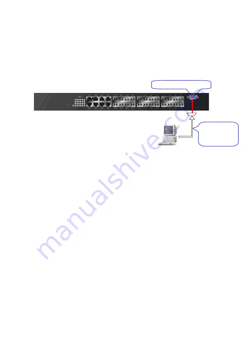
To perform the configuration through RS-232 console port, the switch’s serial
port must be directly connected to a DCE device, for example, a PC, through
RS-232 cable with DB-9 connector. Next, run a terminal emulator with the default
setting of the switch’s serial port. With this, you can communicate with the switch.
In the switch, RS-232 interface only supports baud rate 115200 bps with 8
data bits, 1 stop bit, no parity check and no flow control.
To configure the switch, please follow the procedures below:
1.
Find the RS-232 DB-9 cable with female DB-9 connector bundled.
Normally, it just uses pins 2, 3 and 7. See also Appendix B for more
details on Null Modem Cable Specifications.
2.
Attaches the DB-9 female cable connector to the male serial RS-232
DB-9 connector on the switch.
3.
Attaches the other end of the serial RS-232 DB-9 cable to PC’s serial
port, running a terminal emulator supporting VT100/ANSI terminal with
The switch’s serial port default settings. For example,
Windows98/2000/XP HyperTerminal utility.
Note: The switch’s serial port default settings are listed as follows:
Baud rate
115200
Stop
bits
1
Data
bits
8
Parity
N
Flow
control
none
4.
When you complete the connection, then press
<Enter>
key.
The login
prompt will be shown on the screen. The default username and
password are shown as below:
Username = admin Password = admin
SW24GF L2 Managed Switch
Default IP Setting:
IP address = 192.168.1.1
Subnet Mask = 255.255.255.0
Default Gateway = 192.168.1.254
Terminal or Terminal Emulator
Fig. 2-7
RS-232 cable
with female
DB-9 connector
at both ends
RS-232 DB-9 Connector
Summary of Contents for KGS-2416
Page 2: ......
Page 4: ......
Page 34: ...30 Fig 2 15 Office Network Connection Fig 2 14 Peer to peer Network Connection ...
Page 93: ...89 Fig 3 39 Fig 3 40 Fig 3 41 ...
Page 109: ...105 Fig 3 62 Set up VLAN Tag Priority Mapping Finish ...
Page 116: ...112 Fig 3 67 Ingress Port Fig 3 68 ...
Page 118: ...114 Fig 3 71 Fig 3 72 Fig 3 73 ARP ...
Page 119: ...115 Fig 3 74 ARP Fig 3 75 ARP Fig 3 76 ARP Fig 3 77 ARP ...
Page 120: ...116 Fig 3 78 ARP Fig 3 79 ARP Fig 3 80 ARP Fig 3 81 ARP ...
Page 121: ...117 Fig 3 82 ARP Fig 3 83 ARP Fig 3 84 ARP Fig 3 85 ARP Fig 3 86 ARP ...
Page 122: ...118 Fig 3 87 IPv4 Fig 3 88 IPv4 Fig 3 89 IPv4 ...
Page 123: ...119 Fig 3 90 IPv4 Fig 3 91 IPv4 Fig 3 92 IPv4 Fig 3 93 IPv4 Fig 3 94 IPv4 ...
Page 124: ...120 Fig 3 95 IPv4 Fig 3 96 IPv4 Fig 3 97 IPv4 Fig 3 98 IPv4 Fig 3 99 IPv4 ...
Page 125: ...121 Fig 3 100 IPv4 Fig 3 101 IPv4 Fig 3 102 IPv4 ...
Page 126: ...122 Fig 3 103 IPv4 Fig 3 104 IPv4 Fig 3 105 IPv4 ...
Page 127: ...123 Fig 3 106 IPv4 Fig 3 107 IPv4 Fig 3 108 IPv4 ...
Page 128: ...124 Fig 3 109 IPv4 Fig 3 110 IPv4 Fig 3 111 IPv4 ...
Page 129: ...125 Fig 3 112 IPv4 Fig 3 113 IPv4 Fig 3 114 IPv4 ...
Page 130: ...126 Fig 3 115 IPv4 Fig 3 116 IPv4 Fig 3 117 Action ...
Page 131: ...127 Fig 3 118 Rate Limiter Fig 3 119 Port Copy ...
Page 132: ...128 Fig 3 120 DMAC Filter Fig 3 121 VLAN ID Filter Fig 3 122 VLAN ID Filter ...
Page 144: ...140 Fig 3 124 Wizard Fig 3 125 Set up Policy Rules Fig 3 126 Set up Policy Rules ...
Page 146: ...142 Fig 3 130 Set up Port Policies Fig 3 131 Set up Port Policies ...
Page 147: ...143 Fig 3 132 Set up Port Policies Finish Fig 3 133 Set up Typical Network Application Rules ...
Page 222: ...218 Fig 4 1 Fig 4 2 ...


