


CAUTION
Welding beads, scale and other impurities in the piping
Damage to the pump and shaft seal!
▷
Fit a differential pressure gauge.
▷
Free the piping from any impurities.
▷
If required, fit a filter or clean the strainer.
▷
Comply with the relevant instructions.
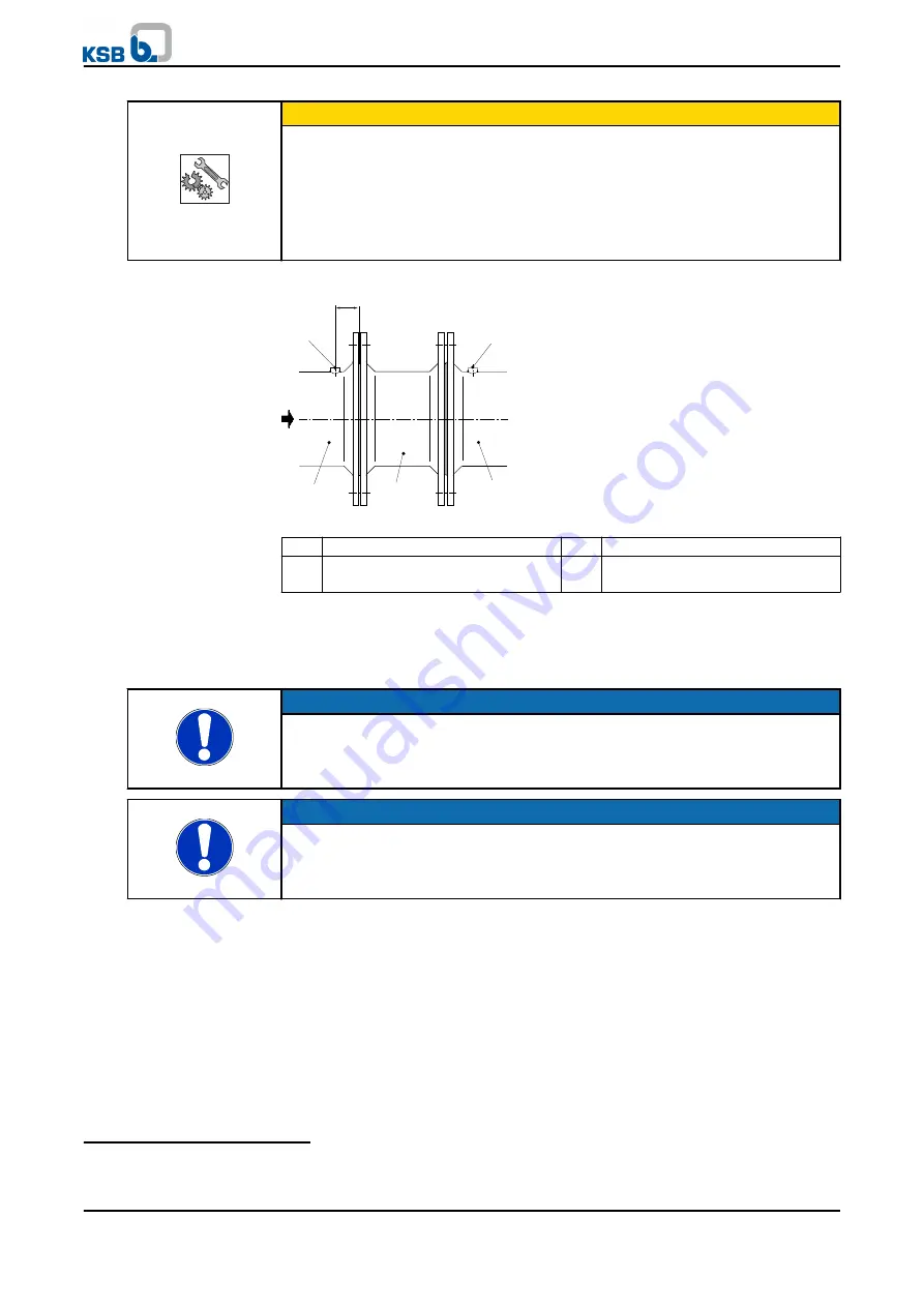
3. If required, install a strainer.
1
2
3
4
4
300 mm
Fig. 7: Installing a strainer
1
Inlet pipe
2
Strainer
3
Suction line, pump
4
Connection for differential
pressure measurement
4. Install the strainer as close as possible to the pump nozzle.
5. Properly drill two holes for connecting the differential pressure measurement
and properly weld on the welding piece.
6)
6. Connect the pump nozzles to the piping.
NOTE
It must be possible to insert all bolts of the discharge nozzle flange into their respective
holes and to remove them from the holes without becoming bolt bound (off-set holes). If
the piping cannot be brought into installation position with one hand, impermissibly high
transverse forces exist.
NOTE
It must be possible to prise apart the flanges of the inlet and discharge lines using a large
screwdriver (~300 mm) to insert the flange seal. If this is not possible, or if the flanges
have to be drawn together by means of the flange bolts, impermissibly high longitudinal
forces exist.
1. Install the bypass control valve
6)
at the pump discharge nozzle, see
manufacturer's product literature.
When installing the bypass line and the balancing liquid line, observe the
minimum flow diagram and/or the Pipe and Instrumentation diagram.
Provide an orifice immediately upstream of the inlet tank to prevent vaporisation
in the bypass line.
1. Arrange the minimum flow system
6)
as shown in the Pipe and Instrumentation
diagram. Perform the installation as described in the manufacturer’s
documentation.
Bypass control valve
Minimum flow system
6)
If any
5 Installation at Site
34 of 78
WKTR


