background image

1 General

5 of 32

4K / 4KD

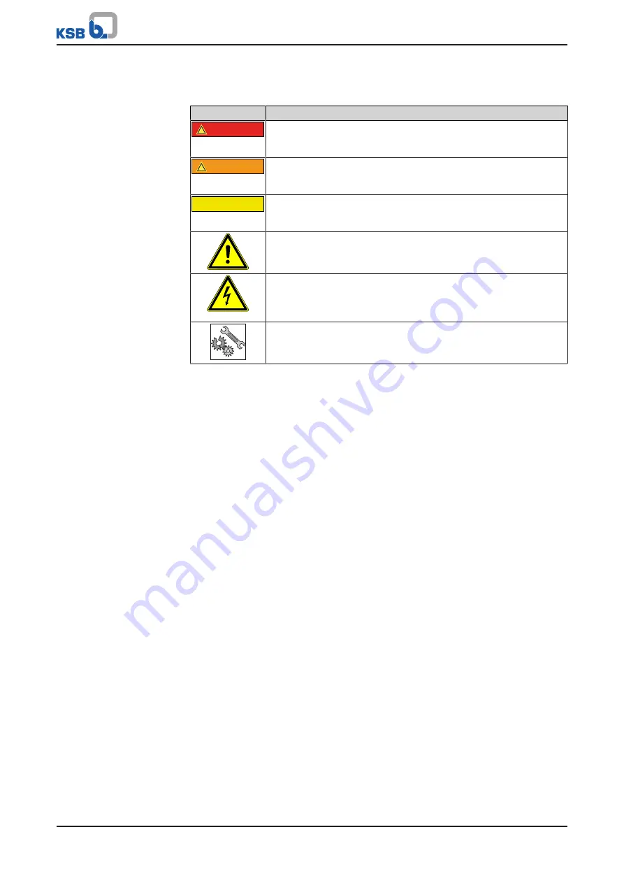
1.5 Key to safety symbols/markings

Table 3: 

Definition of safety symbols/markings 

Symbol

Description

!

DANGER

DANGER


This signal word indicates a high-risk hazard which, if not avoided,
will result in death or serious injury.

!

WARNING

WARNING


This signal word indicates a medium-risk hazard which, if not
avoided, could result in death or serious injury.

CAUTION

CAUTION


This signal word indicates a hazard which, if not avoided, could
result in damage to the machine and its functions.

General hazard


In conjunction with one of the signal words this symbol indicates a
hazard which will or could result in death or serious injury.

Electrical hazard


In conjunction with one of the signal words this symbol indicates a
hazard involving electrical voltage and identifies information about
protection against electrical voltage.

Machine damage


In conjunction with the signal word CAUTION this symbol indicates
a hazard for the machine and its functions.

Summary of Contents for 4K Series

Page 1: ...KSB Mechanical Seal 4K 4KD For the KWP Type Series Installation Operating Manual ...

Page 2: ...nts provided herein must neither be distributed copied reproduced edited or processed for any other purpose nor otherwise transmitted published or made available to a third party without the manufacturer s express written consent Subject to technical modification without prior notice KSB SE Co KGaA Frankenthal 27 03 2018 ...

Page 3: ...rage preservation 8 3 4 Return to supplier 9 3 5 Disposal 10 4 Description 11 4 1 General description 11 4 2 Designation 11 4 3 Materials 11 4 4 Design details 11 4 5 Configuration and function 12 4 6 Flushing adapter 12 5 Installation Dismantling 14 5 1 Permissible aids 14 5 2 Prerequisites 14 5 3 Installing the mechanical seal 15 5 4 Removing the mechanical seal 17 5 5 Tightening torques 18 6 Op...

Page 4: ...nnel 1 3 Other applicable documents Table 1 Overview of other applicable documents Document Contents Data sheet Description of the technical data of the pump set in which the mechanical seal is installed General assembly drawing1 Description of the mechanical seal as part of the sectional drawing of the pump Sub supplier product literature1 Operating manuals and other product literature describing...

Page 5: ...AUTION This signal word indicates a hazard which if not avoided could result in damage to the machine and its functions General hazard In conjunction with one of the signal words this symbol indicates a hazard which will or could result in death or serious injury Electrical hazard In conjunction with one of the signal words this symbol indicates a hazard involving electrical voltage and identifies...

Page 6: ...e technical product literature for the ambient temperature fluid handled speed density pressure temperature and in compliance with any other instructions provided in the operating manual or other applicable documents The product must not be used in potentially explosive atmospheres 2 3 Personnel qualification and training All personnel involved must be fully qualified to transport install operate ...

Page 7: ...nly original spare parts or parts components authorised by the manufacturer The use of other parts components can invalidate any liability of the manufacturer for resulting damage The operator ensures that maintenance inspection and installation is performed by authorised qualified specialist personnel who are thoroughly familiar with the manual Only carry out work on the mechanical seal when the ...

Page 8: ...reement CAUTION Removing transport locks too early Damage to previously locked components during transport If transport locks are fitted do not remove them too early 3 3 Storage preservation We recommend taking the following measures for storing the mechanical seal CAUTION Improper storage Damage during storage due to humidity dirt or vermin Corrosion of and damage to the mechanical seal Avoid out...

Page 9: ...y protected room with constant conditions that meet the following requirements Relative humidity 65 Temperature between 15 C and 25 C Moderately vented atmosphere Dust free and vermin free If properly stored indoors the equipment is protected for a maximum of 36 months New mechanical seals are supplied by our factory duly prepared for storage 3 4 Return to supplier 1 Remove the used mechanical sea...

Page 10: ...id and any fluid residues Wear safety clothing and a protective mask if required Observe all legal regulations on the disposal of fluids posing a health hazard 1 Dismantle the mechanical seal Collect greases and other lubricants during dismantling 2 Separate and sort the mechanical seal materials e g by Metals Plastics Greases and other lubricants 3 Dispose of materials in accordance with local re...

Page 11: ...tion anti clockwise R Direction of rotation clockwise 0 Anti twist lock of mating ring 0 Without lock 1 With lock 4K Type series type 4K Mechanical seal single or in combination with another seal in tandem arrangement with unpressurised buffer fluid API Plan 52 4KD Mechanical seal in combination with another seal in tandem arrangement with pressurised barrier fluid API Plan 53 XW Special designs X...

Page 12: ...specially designed for installing these seals Function Primary ring 472 51 which is the axially movable sealing ring is pressed to the rotating mating ring 475 52 by springs 477 51 O rings 412 51 412 52 and 412 53 are fitted for secondary sealing Thrust ring 474 51 transfers the spring force and torque from casing cover 161 via springs 477 51 and hexagon socket head cap screw 914 to primary ring 4...

Page 13: ...sits 1 Fig 2 4K mechanical seal with flushing adapter 1 Connection for flushing Use Flushing shall be performed before and after any pump shutdown 2 days Once a week for 10 minutes at 10 l min Flushing fluid clean process water maximum contamination of 50 µm Flushing pressure 2 to 4 bar NOTE Prior to every flushing procedure the gap between the rotating shaft sleeve and the thrust ring must be vis...

Page 14: ...not use dirty cleaning cloths or cleaning cloths that leave behind lint CAUTION Impermissible assembly aids Sealing elements made of ethylene propylene rubber perishing or swelling up Never let sealing elements come into contact with mineral oil base lubricants Use permissible lubricants only Verify that the assembly aids are silicon free 5 2 Prerequisites The seal faces are clean and have not bee...

Page 15: ...a ü The original mechanical seal is fully assembled and undamaged 1 Clean the seal faces with a suitable paper tissue and ethyl alcohol 2 Insert thrust ring 474 51 into the turned recess on the rear side of casing cover 161 3 Slide springs 477 51 onto hexagon socket head cap screws 914 4 Thread hexagon socket head cap screws 914 with fitted springs 477 51 through the holes in thrust ring 474 51 an...

Page 16: ...ng 412 55 in seal cover 471 01 7 Dry and clean the seal faces E g with acetone 8 Insert O ring 412 15 into seal cover 471 01 9 Place seal cover 471 01 on studs 902 02 Fasten the studs with nuts 920 02 Make sure the connections are positioned correctly 10 Lift casing cover 161 with seal cover 471 01 and the entire mechanical seal Carefully slide this assembly onto pump shaft 210 and into the bearin...

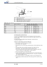
Page 17: ... and reassembly observe the general assembly drawing ð Section 9 1 Page 23 Example of a dismantling sequence for KSB pumps ü The operating manual for the pump is on hand ü The mechanical seal is accessible ü The back pull out unit of the pump has been placed in a clean and level assembly area ü The pump and or machinery has been prepared in accordance with the manufacturer s instructions for disma...

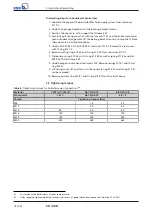
Page 18: ... 412 55 from seal cover 471 01 7 Slide primary ring 472 54 with O ring 412 54 as well as spring 477 54 and disc 500 54 off shaft sleeve 523 8 Undo hexagon socket head cap screws 914 Remove springs 477 51 and thrust ring 474 51 9 Lift casing cover 161 and turn it so that primary ring 472 51 and O ring 412 51 can be removed 10 Remove primary ring 472 51 and O ring 412 51 from the shaft sleeve 5 5 Ti...

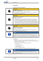
Page 19: ...ive rise in temperature Damage to the mechanical seal Dry running or damage to the elastomers incrustations at the seal faces etc Shut down the pump for safety reasons NOTE If the operating limits indicated are observed and the instructions given in this manual are complied with the mechanical seal can be expected to give trouble free operation If the values during operation are not within the spe...

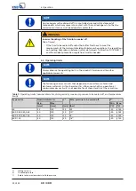
Page 20: ... 6 3 Operating limits NOTE Always observe the operating limits in the product literature and the other applicable documents NOTE The following values are limits that depend on the seal face materials and elastomer materials As the characteristics influence each other operation at minimum maximum limits is not possible for all characteristics at the same time Table 7 Operating limits nominal diamet...

Page 21: ...eplaced as required Proper operation includes regular checks of temperature and leakage drainage of the mechanical seal When a system maintenance inspection is conducted the mechanical seal should also be inspected The seal faces should be reworked and all elastomer joint rings and springs should be replaced by new ones KSB is available for inspecting the mechanical seal ...

Page 22: ...laims for damages NOTE For any failures you cannot remedy or whose cause cannot be identified contact the responsible KSB service centre NOTE Maintenance work servicing work and installation work can be carried out by KSB Service or authorised workshops KSB Service GmbH Service Centre Pegnitz E mail service center sued ksb com KSB Service LLC Service Centre Abu Dhabi E mail ksb ksb ae Contact for ...

Page 23: ...412 51 474 51 477 51 914 Fig 4 General assembly drawing of a 4K Not for nominal diameters 040 050 060 070 Table 8 List of components Part No Description Part No Description 412 51 52 O ring 477 51 Spring for mechanical seal 472 51 Primary ring 523 Shaft sleeve 474 51 Thrust ring 562 Parallel pin 475 52 Mating ring 914 Hexagon socket head cap screw ...

Page 24: ... outlet Required for the mechanical seal to function but not part of the KSB mechanical seal Not for nominal diameters 040 050 060 070 Table 9 List of components Part No Description Part No Description 161 Casing cover 477 51 54 Spring for mechanical seal 230 Impeller 500 54 Ring 412 15 51 52 53 54 55 O ring 523 Shaft sleeve 471 01 Seal cover 562 Parallel pin 472 51 54 Primary ring 902 Stud 474 51...

Page 25: ...l assembly drawing of a 4KXW Not for nominal diameters 040 050 060 070 Table 10 List of components Part No Description Part No Description 412 51 52 O ring 477 51 Spring for mechanical seal 472 51 Primary ring 523 Shaft sleeve 474 51 Thrust ring 562 Parallel pin 475 52 Mating ring 914 Hexagon socket head cap screw ...

Page 26: ...t outlet Required for the mechanical seal to function but not part of the KSB mechanical seal Not for nominal diameters 040 050 060 070 Table 11 List of components Part No Description Part No Description 161 Casing cover 477 51 54 Spring for mechanical seal 230 Impeller 500 54 Ring 412 15 51 52 53 54 55 O ring 523 Shaft sleeve 471 01 Seal cover 562 Parallel pin 472 51 54 Primary ring 902 Stud 474 ...

Page 27: ...quired for the mechanical seal to function but not part of the KSB mechanical seal Not for nominal diameters 040 050 060 070 Table 12 List of components Part No Description Part No Description 161 Casing cover 477 51 54 Spring for mechanical seal 230 Impeller 500 54 Ring 412 15 51 52 53 54 55 O ring 523 Shaft sleeve 471 01 Seal cover 562 Parallel pin 472 51 54 Primary ring 902 Stud 474 51 54 Thrus...

Page 28: ...plain bearing inner rotor has been removed from the pump and cleaned In cases of containment shroud leakage the outer rotor bearing bracket lantern leakage barrier and bearing bracket or adapter have also been cleaned For canned motor pumps the rotor and plain bearing have been removed from the pump for cleaning In cases of leakage at the stator can the stator space has been examined for fluid lea...

Page 29: ... 15 17 Disposal 10 E Event of damage 4 K Key to safety symbols markings 5 O Other applicable documents 4 P Personnel 6 Personnel qualification 6 R Reassembly 15 17 Return to supplier 9 S Safety 6 Safety awareness 7 Specialist personnel 6 T Tightening torques 18 Training 6 W Warnings 5 Warranty claims 4 ...

Page 30: ......

Page 31: ......

Page 32: ...KSB SE Co KGaA Johann Klein Straße 9 67227 Frankenthal Germany Tel 49 6233 86 0 www ksb com 1974 82 01 EN ...

Reviews: