


VAA · Edition 09.21
EN-7
MAIntenAnCe
CAUtIon
In order to ensure smooth operation, check the
device function:
– Check electrical installations once a year in line
with local regulations; pay particular attention to
the PE wire, see page 3 (Wiring).
ACCessoRIes
Pressure switch for gas DG..VC
The pressure switch for gas monitors the inlet pres-
sure p
u
and the outlet pressure p
d
.
➔
Monitoring the inlet pressure p
u
: the pressure
switch for gas is mounted on the inlet side.
Monitoring the outlet pressure p
d
: the pressure
switch for gas is mounted on the outlet side.
p
u
p
d
Scope of delivery:
1 x pressure switch for gas,
2 x self-tapping retaining screws,
2 x sealing rings.
Also available with gold-plated contacts for voltages
of 5 to 250 V.
➔
When retrofitting the pressure switch for gas, see
enclosed operating instructions “Pressure switch-
es for gas DG..C”, section entitled “Mounting the
DG..C.. on valVario gas solenoid valves”.
➔
The switching point is adjustable via hand wheel.
1
2
3
type
Adjusting range
(adjusting
tolerance =
± 15% of the
scale value)
Mean switching
differential at
min. and max.
setting
[mbar]
["WC]
[mbar]
["WC]
DG 17VC
2–17
0.8–6.8 0.7–1.7 0.3–0.8
DG 40VC
5–40
2–16
1–2
0.4–1
DG 110VC 30–110
12–44
3–8
0.8–3.2
DG 300VC
100–
300
40–120
6–15
2.4–8
➔
Deviation from the switching point during testing
pursuant to EN 1854 Gas pressure switches:
± 15%.
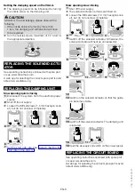
Variable bypass VAA /B
For retrofitting on the VAA, the bypass can be supplied
as an additional item.
Order No.: 74926325
1
Shut off the air supply.
➔
Use the enclosed self-tapping screws and O-rings
for installation.
2
3
4
5
6
teCHnICAL DAtA
Ambient conditions
Icing, condensation and dew in and on the unit are
not permitted.
Avoid direct sunlight or radiation from red-hot surfaces
on the unit. Note the maximum medium and ambient
temperatures!
Avoid corrosive influences, e.g. salty ambient air or SO
2
.
The unit may only be stored/installed in enclosed
rooms/buildings.
The unit is suitable for a maximum installation height
of 2000 m AMSL.
Ambient temperature: -20 to +60°C (-4 to +140°F),
no condensation permitted.
Long-term use in the upper ambient temperature
range accelerates the ageing of the elastomer ma-
terials and reduces the service life (please contact
manufacturer).
Storage temperature: -20 to +40°C (-4 to +104°F).
Enclosure: IP 65.
This unit is not suitable for cleaning with a high-pressure
cleaner and/or cleaning products.